


Norms and Standards


CE CERTIFIED
The CE marking indicates compliance with fundamental health and safety requirements for European Directive 89/686.
The directive divides PPE into three categories, each subject to a different conformity evaluation system:
- Category 1: the manufacturer drafts a technical file and affixes the CE marking without the intervention of an external notified body.
- Category 2: the manufacturer affixes the CE marking after the notified body has performed a type examination on the basis of a technical file.
- Category 3: after the type examination, a notified body conducts a periodic inspection. Manufacturers decide whether the inspection system focuses on product sampling or on an audit of the quality system. Following inspection, the CE marking and the number of the notified body that conducted the inspection must be affixed to the product.
The European Commission describes the CE marking as a “passport” that allows manufacturers to circulate industrial products freely within the internal market of the EU. The CE marking certifies that products have met EU health, safety, and environmental requirements that ensure consumer and workplace safety. All manufacturers in the EU and abroad must affix the CE marking to products covered by the “New Approach” directives to market their products in Europe. Once a product receives a CE marking, it can be marketed throughout the EU without modification.
Most products covered by New Approach Directives can be self-certified by the manufacturer and do not require review by EU-authorized independent testing/certifying companies (i.e., Notified Bodies). To self-certify, the manufacturer must assess the conformity of the products with applicable directives and standards. While the use of EU harmonized standards is voluntary, in practice the use of EU standards is the best way to meet the requirements of the CE marking directives. This is because the standards offer specific guidelines and tests to meet safety requirements, while the directives, general in nature, do not.
The manufacturer may affix the CE marking to their products following the preparation of a declaration of conformity, which indicates that the product meets applicable requirements. Manufacturers must maintain a technical file to prove conformity and they, or their authorized representatives, must provide this together with the declaration of conformity when requested by EU authorities.
If a directive requires the involvement of a Notified Body in the conformity assessment procedure, its identification number must be displayed behind the CE logo. Doing this is the responsibility of the Notified Body.
CE marking is mandatory for certain product groups within the European Economic Area (EEA; the 28 member states of the EU plus EFTA countries Iceland, Norway, and Liechtenstein) plus Switzerland and Turkey. The manufacturer of products made within the EEA and the importer of goods made in other countries must ensure that CE-marked goods conform to all applicable standards.
By affixing the CE marking on a product, a manufacturer is declaring, at its sole responsibility, conformity with all of the legal requirements to achieve CE marking that will permit the free movement and sale of the product throughout the EEA.

EN 342:2017
PROTECTIVE CLOTHING – ENSEMBLES AND GARMENTS FOR PROTECTION AGAINST COLD
(EN 342:2017 supersedes EN 342:2004)
NEN EN 342:2017 specifies requirements and test methods for the performance of clothing ensembles (i.e. g two-piece suits or coveralls) for protection against the effects of cold environments equal to or below -5°C. These effects comprise not only low air temperatures but also humidity and air velocity. The protective effects and requirements of footwear, gloves and separate head wear are excluded from the scope of this standard.
Icler: Insulation value (in M2.K/W) of the single garment or ensemble with standard reference clothing. See table C.2 below for wearing times.
Classes: Classification of the air permeability, see table below (3 levels, where 3 is best).
WP: Indication of resistance to water penetration
Table C.2 – Resultant effective thermal insulation of clothing (Icler) and ambient temperature conditions for heat balance at different activity levels and durations of exposure.
| Insulation Icler (m².K/W) | Wearer moving activity | |||||||||||||||||||
|---|---|---|---|---|---|---|---|---|---|---|---|---|---|---|---|---|---|---|---|---|
| Light 115 W/m² | Medium 170 W/m² | |||||||||||||||||||
| Air velocity | ||||||||||||||||||||
| 0.4 m/s | 3 m/s | 0.4 m/s | 3 m/s | |||||||||||||||||
| 8 h | 1 h | 8 h | 1 h | 8 h | 1 h | 8 h | 1 h | |||||||||||||
| 0.265 | 3 | -12 | 9 | -3 | -12 | -28 | -2 | -16 | ||||||||||||
| 0.310 | -2 | -18 | 6 | -8 | -18 | -36 | -7 | -22 | ||||||||||||
| 0.390 | -9 | -28 | 0 | -16 | -29 | -49 | -16 | -33 | ||||||||||||
| 0.470 | -17 | -38 | -6 | -24 | -40 | -60 | -24 | -43 | ||||||||||||
| 0.540 | -24 | -45 | -11 | -30 | -49 | -71 | -32 | -52 | ||||||||||||
| 0.620 | -31 | -55 | -17 | -38 | -60 | -84 | -40 | -61 | ||||||||||||
Air permeability classes:
| AP (mm/s) | Class |
|---|---|
| 100 < AP | 1 |
| 5 < AP ≤ 100 | 2 |
| AP ≤ 5 | 3 |

EN343:2019
PROTECTIVE CLOTHING: PROTECTION AGAINST RAIN
(NEN-EN 343:2019 supersedes EN 343:2003+A1:2007.)
NEN-EN 343 specifies requirements and test methods for the performance of materials and readymade garments for protection against the effects of precipitation (e.g. rain, snowflakes), fog and ground humidity. Garments for protection against other effects than precipitation (e.g. water splashes, waves) are excluded from this standard. The protective effects and requirements of footwear, gloves and separate headwear are excluded from the scope of this document.
Explanation categories:
X: Water penetration (4 levels, where class 4 is best)
Y: Water vapor resistance / breathability (4 levels, where class 4 is best)
R: Rain tower test (optional) – X: means “not tested”
Below table can be used as a guideline for wearing time due to the breathability.
Recommended maximum continuous wearing time for a complete suit consisting of jacket and trousers without thermal lining.
| Class 1 | Class 2 | Class 3 | Class 4 | |
| Ret > 40 | 25 < Ret ≤ 40 | 15 < Ret ≤ 25 | Ret ≤ 15 | |
| 25 °C | 60 min | 105 min | 180 min | No limit |
| 20 °C | 75 min | 250 min | No limit | No limit |
| 15 °C | 100 min | No limit | No limit | No limit |
| 10 °C | 240 min | No limit | No limit | No limit |
| 5°C | No limit | No limit | No limit | No limit |
| Table valid for medium physiological strain M = 150 W/m², standard man, at 50% relative humidity and wind speed of 0,5 m/s. | ||||

EN 465:1995
PROTECTION AGAINST LIQUID CHEMICALS – PERFORMANCE REQUIREMENTS FOR CHEMICAL PROTECTIVE CLOTHING WITH SPRAY-TIGHT SEAMS BETWEEN DIFFERENT PARTS OF THE CLOTHING (TYPE 4 EQUIPMENT)
(EN 14605:2005 supersedes EN 465:1995.)
This standard specifies the performance requirements for chemical protection clothing with spray-tight seams between the clothing’s parts. Chemical protective clothing must meet the requirements of EN 340 and EN 465.
If risks to the wearer are associated with occasional splashes from corrosive and non-volatile chemicals, type 4 chemical protective clothing is sufficient when worn in combination with protective boots, gloves, and a visor. This apparel and protective equipment provide sufficient protection against commonly encountered acids and alkalis.
Type 4 Equipment:
- Individual jacket, trousers, and good worn in combination
- One-piece suit worn with a separate hood
Manufacturing and expiration dates (formatted as “month and year”) must be added to the clothing’s labels. In addition to the pictogram that denotes the clothing’s resistance to chemicals, the following capacities may be specified (note: a higher number indicates better performance):
- Abrasion resistance class (1 to 6)
- Resistance to heat blocking class (1 or 2)
- Flex cracking resistance class (1 to 5)
- Puncture resistance class (1 to 5)
- Tear resistance class (1 to 5)
- Coating adhesion strength class (1 to 5)
- Resistance to permeation by liquids class (1 to 6)
- Seam strength class (1 to 5)
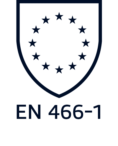
EN 466-1:1995
PROTECTION AGAINST LIQUID CHEMICALS – PERFORMANCE REQUIREMENTS FOR CHEMICAL PROTECTIVE CLOTHING WITH SPRAY-TIGHT SEAMS BETWEEN DIFFERENT PARTS OF THE CLOTHING (TYPE 3 EQUIPMENT)
(EN 14605:2005 supersedes EN 466-1:1995.)
This standard specifies the performance requirement for chemical protection clothing with spray-tight seams between the clothing’s parts. Chemical protective clothing must meet the requirements of EN 340 and EN 466-1.
If risks to the wearer are associated with occasional splashes from corrosive and non-volatile chemicals, type 3 chemical protective clothing is sufficient when worn in combination with protective boots, gloves, and a visor. This apparel and protective equipment provide sufficient protection against commonly encountered acids and alkalis.
Type 3 Equipment:
- One-piece suit worn with an attached hood
Manufacturing and expiration dates (formatted as “month and year”) must be added to the clothing’s labels. In addition to the pictogram that denotes the clothing’s resistance to chemicals, the following capacities may be specified (note: a higher number indicates better performance):
- Abrasion resistance class (1 to 6)
- Resistance to heat blocking class (1 or 2)
- Flex cracking resistance class (1 to 5)
- Puncture resistance class (1 to 5)
- Tear resistance class (1 to 5)
- Coating adhesion strength class (1 to 5)
- Resistance to permeation by liquids class (1 to 6)
- Seam strength class (1 to 5)
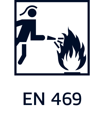
EN 469:2005
PROTECTIVE CLOTHING FOR FIREFIGHTERS – PERFORMANCE REQUIREMENTS FOR PROTECTIVE CLOTHING FOR FIREFIGHTING
(EN 469:2005 supersedes EN 469:1995, EN 469:2006 and will be replaced by EN 469:2015 Development.)
This EU standard specifies the minimum performance requirements for protective clothing worn during firefighting operations and associated activities (e.g. rescue work, assistance during disasters). The standard outlines general clothing design, the minimum performance levels of the materials used, and the test methods used to determine these performance levels. The required performance levels may be achieved by the use of one or more garments. In addition, the standard covers the event of an accidental splash of chemical or flammable liquids but does not cover special clothing for use in other high-risk situations (e.g., reflective protective clothing) nor does it cover protection for the head, hands, and feet and protection against other hazards (e.g., chemical, biological, radiological, and electrical hazards and the hazards encountered during chemical and gas cleaning operations).
The following information must be provided on product labels (note: a higher number indicates better performance):
- The EU standard’s number and year
- The layers of clothing to be used for protection
- Pictogram (see figure)
- If applicable, maximum number of washes before material must be reimpregnated
Pictogram, accompanied by:
- Flame heat transfer index (Xf1 or Xf2)
- Radiant heat transfer index (Xr1 or Xr2)
- Water penetration resistance (Y1 or Y2)
- Water vapour resistance (Z1 or Z2)

EN 471
HIGH-VISIBILITY WARNING CLOTHING FOR PROFESSIONAL USE – TEST METHODS AND REQUIREMENTS
This standard details test methods and performance requirements for clothing designed to enhance the wearer’s visibility in poor and low lighting, during bad weather, and in locations with mechanical hazards. Requirements include very bright colours (e.g., fluorescents) and retroreflective features (i.e., those with high reflectivity).
Design specifications include the minimum required retroreflective surface areas and the configuration of those areas.
- X = classification of the fluorescent and retroreflective material
Classes 1 to 3 (in which 3 is the highest) - Y = classification of the retroreflective material’s quality
Level 1 and 2 (in which 2 is the best)

EN 1149-5:2018
PROTECTIVE CLOTHING – ELECTROSTATIC PROPERTIES – PART 5: MATERIAL PERFORMANCE AND DESIGN REQUIREMENTS
EN 1149-5:2018 specifies material and design requirements for electrostatic dissipative clothing, including hoods and caps, that is worn as part of a total earthed system for protection against incendiary discharges in areas where there is a risk of explosion (ATEX Environments)
Please note that this standard does not encompass protections against hazards associated with mains voltages and oxygen enriched workspaces. This European Standard is not applicable for protection against mains voltages.
The test methods used in EN 1149-5:
- EN1149-1: 2006 measurement of surface resistivity (surface resistance)
- EN1149-3: 2004 measurement of charge decay
- EN1149-4: garment test method (standard currently under development)

EN ISO 11611:2007
PROTECTIVE CLOTHING FOR USE IN WELDING AND ALLIED PROCESSES
(EN 11611 supersedes EN 470-1:1995.)
EN 11611:2007 specifies minimum basic safety requirements and test methods for protective clothing including hoods, aprons, sleeves and gaiters that are designed to protect the wearer’s body, including head (hoods) and feet (gaiters), and that are to be worn during welding and allied processes with comparable risks. EN 11611:2007 does not cover requirements for hand protection.
This International Standard ensures protection against spatter (i.e., small splashes of molten metal), short contact time with flame, radiant heat from an electric arc used for welding and allied processes, and minimizes the possibility of electrical shock by short-term, accidental contact with live electrical conductors at voltages up to approximately 100 V d.c. in normal welding conditions. The garments certified in accordance with this standard are suitable for use in welding and allied processes.
EN 11611:2007 specifies 2 classes with specific performance requirements (class 1 being the lowest level; class 2 the highest).
- Class 1: protection against less hazardous welding techniques and processes, causing lower levels of spatter and radiant heat
- Class 2: protection against more hazardous welding techniques and processes, causing higher levels of spatter and radiant heat
EN ISO 11611:2015
PROTECTIVE CLOTHING FOR USE IN WELDING AND ALLIED PROCESSES
(EN 11611:2015 supersedes EN 11611:2007.)
ISO 11611:2015 specifies minimum basic safety requirements and test methods for protective clothing including hoods, aprons, sleeves, and gaiters that are designed to protect the wearer’s body, including head (hoods) and feet (gaiters), and that are to be worn during welding and allied processes with comparable risks. For the protection of the wearer’s head and feet, this International Standard is only applicable to hoods and gaiters. This International Standard does not cover requirements for foot, hand, face, and eye protection.
This International Standard ensures protection against spatter (i.e., small splashes of molten metal), short contact time with flame, radiant heat from an electric arc used for welding and allied processes, and minimizes the possibility of electrical shock by short-term, accidental contact with live electrical conductors at voltages up to approximately 100 V d.c. in normal welding conditions. The garments certified in accordance with this standard are suitable for use in welding and allied processes.
EN 11611:2015 specifies 2 classes with specific performance requirements (class 1 being the lowest level; class 2 the highest).
- Class 1: protection against less hazardous welding techniques and processes, causing lower levels of spatter and radiant heat
- Class 2: protection against more hazardous welding techniques and processes, causing higher levels of spatter and radiant heat

EN ISO 11612
PROTECTIVE CLOTHING – CLOTHING TO PROTECT AGAINST HEAT AND FLAME
(EN ISO 11612 supersedes EN 531:1995.)
Protection against limited heat and fire, radiation, molten cast.
Markings as followed:
- A1: Limited flame spread – surface ignition
- A2: Limited flame spread – edge ignition
- B: Against convective heat (5 levels)
- C: Against radiant heat (4 levels)
- D: Against molten aluminum (3 levels)
- E: Against molten cast iron (3 levels)
- F: Against contact heat (3 levels)

NEN-EN 1073-2:2002
PROTECTIVE CLOTHING AGAINST RADIOACTIVE CONTAMINATION – PART 2: REQUIREMENTS AND TEST METHODS FOR NON-VENTILATED PROTECTIVE CLOTHING AGAINST PARTICULATE RADIOACTIVE CONTAMINATION.
EN 1073-2:2002 part 2 specifies the requirements and test methods for non-ventilated protective clothing designed to protect the wearer against particulate radioactive contamination.
Results from the inward leakage test can be used to determine the clothing’s Nominal Protection Factor (NPF).
While this type of clothing is intended to protect the wearer’s body, arms, and legs, this clothing may also be worn with accessories – such as boots, gloves, and respiratory protective equipment (RPE) – that provide specialised protection for other areas of the wearer’s body. The requirements for specialised protection are described in other European Standards.
The inward leakage test method is defined in EN ISO 13982-2 Method B and is essentially the same as the Type 5 test, with the highest mean value of Total Inward Leakage for one activity (i.e., the highest TIL(E) percentage and the highest TIL(A) percentage) used to determine the NPF as defined in the table below.
Non-ventilated protective clothing shall be classified according to EN 1073-2:2002
| Class | Mean value of the inward leakage of the three sampling positions inside the suit while standing, walking or squatting – 6 suits: 9 measurements recorded per suit. | Nominal Protection Factor | |
|---|---|---|---|
| One Activity TIL E % | All Activities TIL A % | ||
| 3 | < 0.3 | < 0.2 | 500 |
| 2 | < 3.0 | < 2.0 | 50 |
| 1 | < 30.0 | < 20.0 | 5 |
Class 1 – 3, of which 3 is the highest

EN 13034:2005+A1:2009
PROTECTIVE CLOTHING AGAINST LIQUID CHEMICALS
Performance requirements for chemical protective clothing offering limited protective performance against liquid chemicals (Type 6 and Type PB equipment). This standard specifies the requirements and test methods for Type 6 single- and multiple-use clothing.
Limited performance chemical protective clothing is intended for use in cases of a potential exposure to a light spray, liquid aerosols, or low pressure, low volume splashes, against which a complete liquid permeation barrier (at the molecular level) is not required.
This clothing should be worn in combination with other garments that provide protection as defined in EN 13034.
Chemical protective suits (Type 6) cover and protect at least the wearer’s trunk and the limbs (e.g., one-piece coveralls or two-piece suits, with or without hoods, boot socks, or boot covers).
Partial body protection of similar limited performance (Type PB [6]) covers and protects only specific parts of the body (e.g., coats, aprons, sleeves, etc.).
Type 6 chemical protective clothing provides the lowest level of protection against chemicals and is intended to be used when risks have been assessed as low and a full liquid permeation barrier is not necessary (i.e., when the wearer is able to take immediate and adequate action should their clothing become contaminated). Low risks include potential exposure to small quantities of spray or accidental low volume splashes.
Garments classified in accordance with this standard provide category 3 protections.
Please note: prolonged use of chemical protective clothing can cause heat stress!
All chemical protective clothing material is tested and classified in accordance with requirements listed in Table 1 (see below). To confirm: the construction of seams prevents the penetration of liquid through stitch holes and through other components of a seam and must not obstruct liquid runoff.
| Tests | Test Method | Compliance levels | Minimum Performance Requirements |
|---|---|---|---|
| Abrasion resistance | EN ISO 530-2:2011 | Level 1: ≥ 10 cycles Level 2: ≥ 100 cycles Level 3: ≥ 500 cycles Level 4: ≥ 1000 cycles Level 5: ≥ 1500 cycles Level 6: ≥ 2000 cycles |
Level 1: ≥ 10 cycles |
| Tear resistance trapezoidal | EN ISO 9073-4:1997 | Level 1 > 10 N Level 2 > 20 N Level 3 > 40 N Level 4 > 600 N Level 5 > 100 N Level 6 > 150 N |
Level 1: ≥ 10 N |
| Tensile strength | EN ISO 13934-1:2013 | Level 1 > 30 N Level 2 > 60 N Level 3 > 100 N Level 4 >250 N Level 5 > 500 N Level 6 > 1000 N |
Level 1: ≥ 30 N |
| Puncture resistance | EN 863:1996 | Level 1 > 5 N Level 2 > 10 N Level 3 > 50 N Level 4 > 100 N Level 5 > 150 N Level 6 > 250 N |
Level 1: ≥ 5 N |
| Repellency to liquids | EN ISO 6530:2005 | Level 1 > 80% Level 2 > 90% Level 3 > 95% |
Level 3 ≥ 95% for at least one of the chemicals * |
| Resistance to penetration by liquids | EN ISO 6530:2005 | Level 1 > 1% Level 2 > 5% Level 3 > 10% |
Level 2 ≥ 5% for at least one of the chemicals * |
Chemicals commonly used for the penetration and repellency tests*
- H2SO4 – sulfuric acid (dissolved in water at a concentration of 30%)
- NaOH – sodium hydroxide solution (dissolved in water at a concentration of 10%)
- o-Xylene
- Butan-1-ol
Depending on the purposes for which the garment has been designed, other chemicals may be added to these tests. For example, apparel and PPE created for workforces in the oil, gas, and chemical industries is generally tested in accordance with EN ISO 13034.

EN ISO 13688
PROTECTIVE CLOTHING – GENERAL REQUIREMENTS
(EN ISO 13688:2013 supersedes EN 340:2004.)
The standard specifies general performance requirements for ergonomics, innocuousness, size designation, aging, compatibility, and marking of protective clothing and the information to be provided by the manufacturer with the protective clothing. This standard shall be used in combination with other standards containing requirements for specific performance.
More detailed, general requirements for protective clothing include:
- Innocuousness of the materials to the wearer.
- Ergonomic requirements for the clothing including comfort, weight, and design considerations.
- The effect of wear and tear on product performance (e.g., colour alteration, cleaning, and changes in dimension).
- Sizing is based on height, chest and waist circumferences, is standardized in accordance with EN 3635, and is detailed in the sizing pictogram that is included on each product’s label. EN ISO 13688 specifies that sizing intervals should not be standardized and instead favors a “flexible” approach.
• Labels must be visible and legible, be written in the official language of the country of destination, and include the following information:
a) Name, trademark, or other means of manufacturer identification
b) The product’s commercial name or codec) A pictogram and size designation according to EN 3635
d) Reference to the specific EU protective clothing standard
e) A pictogram showing the hazard the product is designed to protect the wearer against and the product’s performance level
f) Composition, care, and washing instructions using care symbols in accordance with EN 3758
• Instructions for the wearer must be written in the official language of country to which the products are being shipped and must include the following information:
a) Identification and address of manufacturer
b) Identification and address of the notified body (PPE categories 2 and 3)
c) Reference to the specific EU protective clothing standard
d) A pictogram showing the specific hazard the product is design addresses and the product’s performance level
e) The product’s material composition
f) Information to the wearer specifying safety checks that must be conducted prior to use, the purpose and limitations of the product (e.g., how long the product can be used in specific working conditions), and storage, maintenance, and cleaning instructions
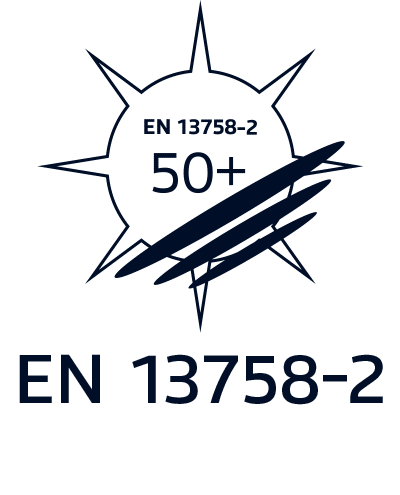
EN 13758-2:2003+A1:2007
Textiles – Solar UV protective properties – Part 2
EN 13758-2:2003+A1:2007 – Textiles – Solar UV protective properties – Part 2: Classification and marking of apparel supersedes EN 13758-2:2003+A1:2006 Textiles – Solar UV protective properties – Part 2: Classification and marking of apparel.
This European Standard specifies the requirements for marking of clothing which are designed to offer the wearer protection against solar ultraviolet radiation exposure.
EN 13758-2 is a product standard that protects the skin against the sun’s harmful UVA and UVB rays. Clothing that is certified with this standard is marked with an ultraviolet protection factor (UPF-value), which indicates the level of protection provided.
Prolonged exposure to the sun can cause skin damage. Wearing protective apparel designed in accordance with this standard reduces the dangers caused by UV exposure. While this apparel protects against UV radiation, wearing this apparel does not guarantee protection in all conditions. Note that only areas covered by this apparel are protected and that the degree of protection provided by this apparel may reduce as the apparel is used, stretched, or wet. UV protective apparel should be cared for according to the instructions provided inside each garment.
Protection categories
| UPF* range | Protection | % UV blocking | Rating |
| 15 – 24 | Good | 93,3 – 95,8% | 15,20 |
| 25 – 39 | Very good | 96 – 97,4 % | 25,30,35 |
| 40 – 50+ | Excellent | 97,5 – 98+% | 40,45,50,50+ |
*UPF – Ultraviolet Protection Factor

EN ISO 13982-1:2004+A1:2010
Protective clothing for use against solid particulates – Part 1: Performance requirements for chemical protective clothing providing protection to the full body against airborne solid particulates (type 5 clothing)
EN ISO 13982-1:2004+A1:2010 supersedes EN ISO 13982-1:2004+ Development A1:2009.
This part of EN ISO 13982 specifies the minimum requirements for chemical protective clothing resistant to penetration by airborne solid particulates (type 5). These garments provide full-body protection (i.e. they cover the trunk, arms, and legs; e.g., one-piece coveralls or two-piece suits, with or without hoods or visors and with or without foot protection). Requirements for component parts, such as hoods, gloves, boots, visors, or respiratory protective equipment are specified in other International and European Standards.
This part of EN ISO 13982 is applicable only to airborne solid particulates. It is not applicable to other hazards created by solid chemicals (e.g. penetration of chemical dust through materials by rubbing or flexing; countering such hazards form the bases for separate standards).
Information needed on labelling inside type 5 garments:
- manufacturer/company name
- identification or model number
- number and date of this standard (i.e. EN ISO 13982-1:2004+A1:2010)
- year of manufacture and, if appropriate, expected shelf-life
- CE marking indicating conformity with the Regulation EU 2016/425
- size designation in conformance with EN ISO 13688 General Requirements*
- pictogram chemical splash – type 5 and, if tested, type 6
- pictogram for “read instructions”
- maintenance symbols
- marked according to relevant standards if the garments are tested for their electrostatic properties or as radioactive particle-tight clothing, clothing providing protection against infective agents, and clothing resistant to heat and flame
- PPE category
*EN 340:2003 was replaced with EN ISO 13688:2013. Although this change is not yet reflected in EN ISO 13982-1, the required tests are essentially the same, and either reference is expected to be accepted by the notified body certifying the product.

EN 14058:2017
PROTECTION AGAINST COLD – GARMENTS FOR PROTECTION IN COOL ENVIRONMENTS
(EN 14058:2017 supersedes EN 14058:2004)
This standard specifies the requirements and test methods for evaluating the performance of single garments that provide protection against the cooling of the wearer’s body in areas where the air temperature can be as low as -5 °C. The standard does not include specific requirements for headwear, footwear, or gloves.
Many work activities are carried out in cool environments. For example, outdoor construction work or indoor food processing jobs. The type of clothing tested to EN 14058 includes waistcoats, jackets, and trousers, and separate thermal linings that can be added to a garment.
A “cool environment” is characterized by a combination of humidity, wind, and temperatures as low as -5°C. Some garments provide adequate protection against local body cooling (for ensembles, see EN 342) relative to the length of the wearer’s exposure to the cold, the wearer’s physiology, the composition of the wearer’s overall outfit, and specific environmental features (e.g., wind speed, temperature, humidity).
At moderate to low temperatures, garments that protect against local body cooling can be used for outdoor and indoor activities. In these instances, garments need not be made of watertight or air impermeable materials; these requirements are, then, optional for this standard. EN 14058 defines 1 criterion to ensure the proper functioning of protective clothing against the hazards of cool environments:
Thermal resistance (Rct) represents a quantity specific to textiles and indicates the amount of dry heat that can pass through a textile layer in a steady state condition as a result of a temperature gradient.
Performance requirements for air permeability (AP), thermal insulation (Icler) and resistance to water penetration (WP) are optional and measured with the same criteria as EN 342.
Parameters:
a: thermal resistance (Rct), classes 1 – 4
b: air permeability (AP), classes 1 – 3 (optional, only for outdoor clothing)
c: thermal insulation value (Icler) in m²K/W (optional for thermal resistance classes 1-3, mandatory if Rct exceeds class 4)
d: water penetration resistance (WP) min 8000Pa (optional)

EN 14605:2005
PROTECTIVE CLOTHING AGAINST LIQUID CHEMICALS – TYPE 3 OR 4
(EN 14605:2005 supersedes EN 467:1995, EN 465:1995, EN 466-1:1995.)
This standard specifies performance requirements for clothing with liquid-tight (type 3) or spray-tight (type 4) seams and includes requirements for apparel that provides protection for specific parts of the body only (types PB [3] and PB [4]).
Types 3 and 4: Differences and Applications – Implications of Permeation Testing (EN 374-3 or ISO 6529)
The key difference between types 3 and 4 relates to the pressure and volume of a liquid spray:
- Type 3 is a strong jet of liquid such as that from a pressure sprayer
- Type 4 is a lighter spray such as that from a sprinkler system (i.e., substantial volume but lower in pressure)
In EN 14605 certification testing, this difference is reflected primarily in the finished garment spray test and not by any comparative mechanical property or by chemical permeation or barrier assessment tests.
Both types 3 and 4 must have sealed seams. EN 14605 requires at least one chemical permeation test on a seam (as well as the fabric) with a minimum score in class 1 (i.e. >10 minutes). No type of stitched seam will achieve this result against any chemical.
Type 3 and 4 certification also requires a permeation test on the fabric against at least one chemical with a minimum score in class 1 (i.e. >10 minutes). This standard does not specify that any particular chemical must be used for this test so, theoretically, a garment could be certified to type 3 or 4 with a permeation test against, for example, water while showing a normalised breakthrough of 11 minutes. However, a fabric with such a poor barrier against water would be unlikely to pass the finished garment spray tests.
Certification to types 3 and 4 does not indicate a general suitability for protection against any specific chemical or a general chemical protective application. An assessment of the permeation barrier against specific chemicals should be made as part of every risk assessment.
Permeation classification:
- Class 1 > 10 min
- Class 2 > 30 min
- Class 3 > 60 min
- Class 4 > 120 min
- Class 5 > 240 min
- Class 6 > 480 min

EN ISO 14116:2015
Protective clothing – Protection against flame – Limited flame spread materials, material assemblies and clothing
EN ISO 14116:2015 supersedes EN ISO 14166:2008
EN ISO 14116 specifies the performance requirements for the limited flame spread properties of all materials, all material assemblies, and protective clothing in order to reduce the possibility of the clothing burning when in occasional and brief contact with small flames in locations where there is no significant flame hazard or the presence of other heat types.
Additional requirements for clothing are also specified, including design requirements, mechanical requirements, marking, and information supplied by the manufacturer.
When protection against heat hazards is necessary, in addition to protection against flame, this International Standard is not appropriate. International Standards such as ISO 11612 are to be used instead.
According to the EN ISO 14116:2015 standard, the protective clothing related to this standard must be flame retardant, therefore non-flammable or delaying or reducing the possibility of combustion so that it burns and can become dangerous for the wearer.
A classification system is given for materials, material assemblies, and garments which are tested according to ISO 15025, Procedure A. This standard divides garments into three different index levels based on specific tests, index level 3 is the highest:
| Index level | Explanation |
| Index 1 | The flame should not spread, should not generate flaming residue, and there should be no residual glow |
| Index 2 | The flame must not spread, must not generate flaming residues, there must be no residual glow and the fabric must be free of holes |
| Index 3 | The flame must not spread, must not generate flaming residues, there must be no residual glow, the fabric must be free of holes and must not show deterioration for at least the first two seconds of exposure to the flame |
Protective clothing, according to EN ISO 14116, may consist of separate garments worn in combination or a single garment with one or more layers. To comply with this standard, all material assemblies must achieve a limited flame spread index of 1, 2, or 3 when tested in accordance with ISO 15025.
A category 1 garment must be worn over category 2 or 3 clothing and cannot come into contact with the skin.
Explanation difference between EN ISO 14116:2008 vs EN ISO 14116:2015
| EN ISO 14116:2008 | EN ISO 14116:2015 | |
| Shell fabric | Index 1 | Index 1 |
| Trimmings | No requirements | Index 1 |
| Parts which touch the skin | Index 1 = accepted, with advice to wear Index 3 underwear. | Index 3 (collar, hood). Index 1 fabric is not allowed to touch the skin anymore. |
In the past it was accepted to inform what to wear below the jacket in the User Instruction. For the updated norm, this is not acceptable any more.
The parts that touch the skin should be made of fabric with index 3. Also, the trimmings should have same index as the fabric, index 1. This mean the trimmings should be of FR quality.

EN ISO 15025:2000
PROTECTIVE CLOTHING – PROTECTION AGAINST HEAT AND FLAME – TEST METHODS FOR LIMITED FLAME SPREAD
This standard, superseded by ISO 15025:2016, specifies the methods for measuring the limited flame spread properties of vertically-oriented textiles and industrial products in the form of single or multi-component fabrics (e.g., coated, quilted, multilayered, sandwich constructions, and similar combinations) when subjected to a small, intense flame. These test methods are not appropriate for materials that melt or shrink extensively.
These methods include two procedures:
Procedure A: surface ignition
- Position the burner perpendicular to the surface of the test fabric
- Align the axis of the burner 20mm above the line of the lower pins
- Adjust the horizontal reach of the flame to 25 mm
- Test six specimens of fabric
Procedure B: bottom edge ignition
- Position the burner below the test specimen
- Adjust inclination to a 30° angle and flame height to 40 mm
- Test six specimens of fabric
After 10 seconds of ignition, the lab must note:
- whether the flame reaches any edge of the test fabric
- the after flame time
- whether afterglow spreads to the undamaged area
- the afterglow time
- the occurrence of debris
- whether a hole develops

Procedure A Procedure B
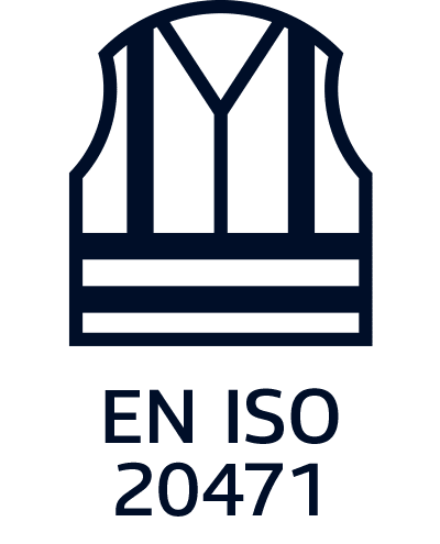
EN 20471:2013
HIGH-VISIBILITY CLOTHING
(EN 20471:2013 supersedes EN 471:2003/A1:2008.)
In contrast to EN 471, ISO 20471 has one value (x), which indicates the class of the product. Since reflection is featured only in the highest class, the value (y) expires in ISO 20471. High-visibility clothing requirements increase visibility during the day, twilight, in the dark, and in poor weather conditions. High-visibility clothing has a fluorescent surface and retroreflective material that meet the certification requirements of three different classes. The applicable performance class can be obtained using a single garment or a clothing ensemble (e.g., jacket and trousers). Performance requirements are included for colour, retroreflection, and minimum HV surface area. The standard also includes direction concerning where to place HV features on protective clothing.
Classification:
- X: ratio of fluorescent background material to retroreflective material (3 levels, where 3 is best)

EN-IEC 61482-2:
2020 Protective clothing against the thermal hazards of an electric arc.
EN IEC 61482-2:2020 supersedes IEC 61482-2:2009.
This part of EN 61482 specifies requirements and test methods applicable to materials and garments for protective clothing for electrical workers against the thermal hazards of an electric arc. Electric shock hazards and other effects like noise, light emissions, pressure rise, hot oil, the consequences of physical and mental shock or toxic influences are not covered by this standard. Protection of eyes, face, head, hands, and feet against electric arc hazard fall outside the scope of this standard.
EN-IEC 61482-2 includes two methods for testing. Garments can be certified according to one of the test methods or to both test methods.
Arc Testing Methods:
- EN-IEC 61482-1-1:2019 supersedes IEC 61482-1:2009 – “Open Arc Test Method” (used in the USA)
The Open Arc test method (ATPV test and garment test) determines the Arc Rating Arc Thermal Protection Value (ATPV level), ELIM (incident energy limit) or Energy Break Open Threshold (EBT) of flame-resistant material (Method A) and clothing (Method B). The basic principle is that the ATPV of the garment must be higher than the Arc Flash energy level as calculated. The “Open Arc” test method is the same as the original North American method for measuring the Arc Thermal Performance Value (ATPV) as used in ASTM F1959. The Arc Rating is expressed in cal/cm² (calories per centimetre square).
- EN-IEC 61482-1-2:2015 – “Box Test Method” (used in Europe)
In the Box Test Method, materials and clothing will be tested using two methods: the material box test method and the garment box test method.
- The material box test method is used to measure and determine material response to an arc exposure when tested in a flat configuration. A quantitative measurement of arc thermal performance is made by means of the energy transmitted through the material. During this test, a fabric sample is exposed to an electric arc produced by a 4kA or 7kA short circuit. In this test, the arc does not last any longer than 500ms. The amount of heat transmitted through the sample is measured during and after the test. Based on the resulting data and a Stoll curve, the length of time it would take to cause the onset of second-degree burns is subsequently determined. Samples are also assessed for after-flaming, hole formation, melting, etc.
- The garment box test method is used to test the function of the protective clothing after an arc exposure (i.e., no heat flux will be measured). This test must be conducted on a complete garment. In doing this, the objective is not to determine the energetic value, but to assess the garment after exposure to an electric arc for defects in the seams, fastenings, and other closures,
The garments are tested and evaluated in two classes in the same test:
APC1 (Arc protection class) protects against electric arc of 4kA (arc energy 168 kJ)
APC2 protects against electric arc of 7kA (arc energy 320 kJ)
AS/NZS 1906.4:2010
RETRO-REFLECTIVE MATERIALS AND DEVICES FOR ROAD TRAFFIC CONTROL PURPOSES – HIGH-VISIBILITY MATERIALS FOR SAFETY GARMENTS
This standard specifies requirements for high-visibility materials capable of signalling the user’s presence visually. The standard describes the requirements for and physical properties of photometric and colorimetric high-visibility materials for use outdoors during daylight hours (class F), retro-reflective materials for use at night or in other low-light conditions (class R), and a combination of the two.
Classes:
- Class F – High daytime visibility fluorescent material/ fabric.
- Class F (W) – High daytime visibility fluorescent material that has met both the requirements for Class F material and an optional wet weather test.
- Class R – Retro-reflective material for use in garments used in low-light conditions.
- Class RF – Combined performance retro-reflective/fluorescent material that meets the requirements of Class R and the daytime colour of Class F.
- Class NF – High daytime visibility non-fluorescent material.
AS/NZS 4399:2017
SUN PROTECTIVE CLOTHING
AS/NZS 4399:2017 supersedes AS/NZS 4399:1996.
Protective clothing that provides protection against solar ultraviolet radiation exposure (UVA and UVB).
This Standard is intended to provide information to the consumer on the relative capability of materials and items of clothing to provide protection against solar ultraviolet radiation (UVR).
This information is provided to the consumer in the form of a labelling scheme based on an objective, reproducible test method.
This standard is used to determine the ultraviolet protection factor of textiles and similar materials (e.g., protective films) in a new conditions without real usage.
What are the major changes in the revised standard?
Major changes in the 2017 edition of the standard are:
- A minimum level of body coverage is required for clothing to display or claim a UPF rating
- A revised UPF classification system and labelling requirements
- Minimum requirements for hats, gloves, and accessories
The standard excludes clothing with low body coverage, such as bikini swimwear, from making any sun protection claims regardless of the UPF rating of the material that the clothing is made from. Other excluded items due to inadequate body coverage include singlets, crop tops, halter tops, and briefs.
What are the changes to the UPF classification system?
The classification system has been reduced to just four UPF ratings from the nine protection categories in the 1996 edition. The names of the protection categories have also changed and are now called ‘classifications.
| UPF rating | Classification | % UV radiation blocked |
| 15 | Minimum | 93.3 |
| 30 | Good | 96.7 |
| 50, 50+ | Excellent | 98 |
What are the minimum requirements for hats, gloves, and accessories?
Gloves, wraps, blankets, helmet flaps and women’s one-piece swimsuits may be promoted as being sun protective depending on design. Gloves are only considered sun protective if they cover the entire back of the hand to the wrist.
The revised standard specifies three types of hats which are considered sun protective —bucket hats, legionnaire hats and broad-brimmed hats which have brims wider than a specified minimum width (the diagram below is from the standard). There is allowance for alternative types of hats which fulfil certain protection requirements. Caps and sun visors are excluded.
Note: In Australia, the sun protective clothing standard has been revised as: AS 4399:2020, however Standards New Zealand did not have New Zealand manufacturers or retailers’ express interest in participating in the review and thus the revised standard did not include Standards New Zealand and the AS/NZS 4399:2017 remains current in New Zealand.

AS 4399:2020
Sun Protective Clothing
This Standard is intended to provide guidance regarding the information communicated to the consumer on UPF labels and/or swing tags about the relative sun protective capability of material and items of clothing. This information is intended to assist the consumer in the selection of those items which best suit their need for sun protection. This Standard also specifies the minimum level of body coverage that an item of clothing needs to achieve in order to legitimately display or claim an UPF rating.
Standards Australia has released a revision to the Australian and New Zealand standard for sun protective clothing, AS 4399 Sun protective clothing – Evaluation and classification.
As some of the changes in the revised standard may impact manufacturers of sun protective clothing, the important differences between the 2017 and 2020 editions of the standard are summarized below. The information presented here is only a brief summary of the changes in the standard, and manufacturers are advised to familiarize themselves with the information about body coverage, Ultraviolet Protection Factor (UPF) claims and labelling in the revised standard.
Major changes in the 2020 edition of the standard are:
- This is now an Australian standard, and is no longer a joint standard with Standards New Zealand.
- Removal of the exemption for women’s swimwear.
- Minimum brim requirements for hats have been clarified.
- Allows an exception for all-in-one clothing that meets either all the upper body, or all the lower body coverage requirements, to claim a UPF rating with specific labelling to be applied.
- Revised UPF classification system and clarification on labelling requirements.
- Umbrellas and shade structure suppliers/users are referred to AS 4174 Knitted and woven shade fabric standard.
Update on body coverage requirements for clothing
The main change to the body coverage requirements are around the removal of women’s one-piece swimsuit exemption. Women’s one-piece swimsuits may no longer be promoted as being sun protective unless they meet the body coverage requirements.
There was also clarification on UPF claims and labelling of all-in-one clothing that does not fully cover both the upper and lower body coverage requirements. Exceptions for all-in-one clothing, provided the body coverage meets at least all of the upper body or all of the lower body coverage requirements, are permitted to make UPF claims. Specific labelling is required for these products.
Clarification on minimum requirements for hats
The revised standard clarifies the minimum brim dimensions for the three types of hats which are considered sun protective – bucket hats, legionnaire hats and broad-brimmed hats. There is allowance for alternative types of hats which fulfil certain protection requirements. Caps and sun visors are still excluded.
Revised UPF classification system
The UPF classification system has been modified to remove the “effective ultraviolet radiation (UVR) penetration” column, and the word “protection” is to be added after the classification of minimum, good and excellent. The standard now provides clearer guidance on labelling, including additional labelling for items not meeting the minimum body coverage requirements.
When will the revised standard come into effect?
The AS 4399 is not a mandatory standard, so there isn’t a specific implementation date for changing to the revised standard, but it is reasonable to change over within one year of the publication date. No action is required for products already tested and labelled according to the 2017 edition of the standard.
ASTM F1506-20a
Standard Performance Specification for Flame Resistant and Electric Arc Rated Protective Clothing Worn by Workers Exposed to Flames and Electric Arcs
This performance specification covers the design characteristics and associated test methods that relate specifically to the flame resistance of textile materials used in the fabrication of basic protection level occupational apparel worn by electrical workers who are exposed to momentary electric arc and related thermal hazards such as exposure to open flame and radiant heat. When evaluated in accordance with the test procedures enlisted herein, knit fabrics and woven fabrics of different fabric weights shall conform to individually specified values of the following properties: colorfastness such as laundering shade change, dry-cleaning shade change, and dimensional change; initial flammability characteristics and flammability characteristics after 25 washes/dry-cleaning such as char length and after-flame time; and arc test rating. Knit fabrics shall additionally be tested and adhere accordingly to bursting strength characteristics. Conversely, woven fabrics shall also be tested and adhere accordingly to breaking load, tear resistance, and seam slippage characteristics.
Scope
1.1 This performance specification identifies minimum performance requirements to determine the (a) arc rating of fabrics, (b) flame resistance of fabrics and subassemblies, (c) mechanical durability of the fabrics and subassemblies, (d) the minimum garment construction and performance requirements, and (e) the garment labeling requirements for the completed protective clothing worn by workers exposed to flames and electric arcs.
1.1.1 The minimum requirements for garment labeling are intended to provide end users with adequate information to select garments with the appropriate arc rating.
1.1.2 End users are required to perform an assessment to determine the level of hazard and the required arc rating of the protective clothing for their individual hazards.
1.1.2.1 The end user risk assessments are outside the scope of this standard.
1.2 This performance specification does not address coated or laminated protective clothing commonly used for rainwear applications in an arc hazard environment. Performance requirements related to this category of protective clothing are detailed in Specification F1891.
1.3 This performance specification does not address hand protection. Performance and test requirements related to hand protection are detailed in OSHA 1910.138, Specification D120, and Test Method F2675/F2675M.
1.4 The care and maintenance requirements for laundering electric arc flash protective clothing are outside the scope of this standard. Refer to Guides F1449 or F2757 related to industrial or home laundering.
1.5 This standard should be used to evaluate and describe the properties of materials, products, or assemblies in response to heat and flame under controlled laboratory conditions. It should not be used to describe or appraise the fire hazard or fire risk of materials, products, or assemblies under actual fire conditions.
1.5.1 The results of this evaluation may be used as elements of a fire-risk assessment that takes into account all of the factors that are pertinent to an assessment of the fire hazard of a particular end use.
1.6 The values stated in SI units are to be regarded as the standard. The values given in parentheses are for information only.
1.7 The following precautionary caveat pertains only to the test methods portion, Section 7, of this performance specification: This standard does not purport to address all of the safety concerns, if any, associated with its use. It is the responsibility of the user of this standard to establish appropriate safety, health, and environmental practices and determine the applicability of regulatory limitations prior to use.
1.8 This international standard was developed in accordance with internationally recognized principles on standardization established in the Decision on Principles for the Development of International Standards, Guides and Recommendations issued by the World Trade Organization Technical Barriers to Trade (TBT) Committee.
ANSI/ISEA 107-2020
HIGH VISIBILITY SAFETY APPAREL
The American National Standard for High-Visibility Safety Apparel (ANSI/ISEA 107-2020) is a standard established by American National Standards Institute Inc.
This standard provides guidelines for the selection and use of high-visibility safety apparel (HVSA) such as shirts, rainwear, outerwear, and safety vests to help improve worker visibility during the day, in low-light conditions, and at night.
Personnel and many categories of off-road workers are routinely exposed to potential injury hazards from their low visibility.
ANSI 107 keeps off-road (“Type O”), roadway (“Type R”), and public safety (“Type P”) garments separate by application and aligns with the definitions of the U.S. Federal worker high-visibility regulation implemented in the MUTCD.
TYPE O (OFF-ROAD)
Type O features a single Performance Class (Class 1) and is intended for off-road use, often indoors or more controlled environments.
Examples: Among others, workers retrieving shopping carts, working in warehouses and factories or extracting/refining oil & gas.
TYPE R (ROADWAY)
Type R offers a Performance Class 2 and Class 3—garments specifically designed for use on roadways—and is often the choice of other construction and transportation applications due to the high presence of moving vehicles and equipment. Because Type R features more fluorescent background material and additional retroreflective square inches, it is better suited for environments with higher levels of moving vehicle and equipment traffic. For workers in the right of way of a roadway, it’s required by federal law.
Examples: A Type R Class 2 vest, for instance, would serve road construction workers, airport ramp workers or municipality workers.
Class 3, meanwhile, is meant to be used in applications such as flaggers and DOT workers with high-speed traffic hazards who are unable to devote attention to the environment around them.
TYPE P (PUBLIC SAFETY)
Like Type R, Type P has a Performance Class 2 and Class 3 for public safety with Class 3 garments requiring more background and retroreflective material. Public Safety vests and jackets are typically shorter length to enable quick and easy access to equipment carried on the waist (i.e., firearms for police officers).
Examples: First responders/public safety figures such as police, fire, and EMS.
In general, material specifications on hi-vis apparel dictated by Garment Types and Performance Classes are directly proportional to the speed of and proximity to traffic/moving vehicles and equipment around each type of worker. That’s why road construction workers building or repairing highways should wear Type R Class 2 or Class 3 garments while indoor warehouse workers or attendants working parking lots where cars are neither driving fast nor nearby could choose to wear a Type Class 1 O option.
ANSI/ISEA 107-2020 UPDATES
Formerly ANSI/ISEA 107-2015, ISEA’s High Visibility Products Group recently reviewed and updated the standard to ANSI/ISEA 107-2020.
Notable changes include:
- Criteria for hi-vis accessories has been removed: The standard no longer includes criteria for the optional accessory category.
- Additional criteria on 360-degree reflective visibility + revised definition of “torso area”: Each Type and Performance Class now has further clarification on the width requirements for retroreflective and background material around the wearer’s torso. Additionally, torso has been defined as “the trunk of the body extending from the underarm to hip area.”
- Maximum wash cycles no longer required on care label: The max number of wash cycles was previously based on the life of the reflective—not the entire garment. This was removed to avoid confusion about the depreciation of high visibility apparel in general.
- Testing requirements for segmented or perforated tape: Given the increased popularity of segmented and perforated retroreflective, the standard now includes additional requirements for the retro reflectivity of background materials used when testing these segmented materials. This is intended to prevent manufacturers from overstating the brightness of the tape.
NFPA 70E
STANDARD FOR ELECTRICAL SAFETY IN THE WORKPLACE
NFPA 70E helps companies and employees avoid workplace injuries and fatalities due to shock, electrocution, arc flash, and arc blast. Employees’ equipment contains flame-resistant clothing, which meets the requirements of ASTM F1506.
The NFPA 70E standard provides tables of common electrical tasks, which are assigned one of five Hazard Risk Categories (HRC 0, 1, 2, 3 or 4). Each HRC category has a minimum arc rating for protective clothing measured in cal/cm² plus other PPE requirements.
Arc Thermal Performance Value (ATPV), a value of the energy necessary to pass through any given fabric to cause with 50% probability a second- or third- degree burn. This value is measured in calories/cm². ATPV indicates the level of protection provided by flame-resistant clothing as measured in cal/cm²: the higher the ARC rating, the greater the protection.
Hazard Risk Category (HRC) is the level of arc flash protection clothing you must wear to protect against a minimum level of incident energy measured in calories per centimetre squared.
HRC 1 (low risk), up to HRC 4 (high risk, requiring FR clothing with a minimum arc rating of 40). The HRC is used to determine the necessary arc rating of a garment worn during a given job task. Wearing multiple layers of clothing may be required to obtain the necessary rating for your work.
NFPA 2112:2012
STANDARD ON FLAME-RESISTANT GARMENTS FOR PROTECTION OF INDUSTRIAL PERSONNEL AGAINST FLASH FIRE
Standard for Flame-Resistant (FR) Garments for Protection of Industrial Personnel against Flash Fire
This standard specifies the minimum performance requirements and test methods for FR fabrics and components and the design and certification requirements for garments developed to protect workers from a flash fire hazard. It requires FR fabrics to pass a comprehensive number of thermal tests.
Including the following tests:
- ASTM D6413 – Vertical Flammability Test – maximum 2.0 seconds after flame and 4.0 inch char length.
- ASTM F1930 – Thermal Mannequin Test – maximum predicted body burn after 3.0 second thermal exposure.
- ASTM F2700 – Heat Transfer Performance (HTP) test – minimum HTP of 6.0 cal/cm2 spaced and 3.0 cal/cm2 contact.
- Thermal Stability Test – fabric must not melt or drip, separate or ignite after 2.0 minutes in a 260° C (500° F) oven.
- AATCC 135 – Thermal Shrinkage Test – fabric must not shrink more than 10% after 5.0 minutes in a 260° C (500° F) oven.


EN 374-1:2003
GLOVES PROVIDING PROTECTION AGAINST CHEMICALS AND MICROORGANISMS – PART 1: TERMINOLOGY AND PERFORMANCE REQUIREMENTS
This standard specifies the requirements for gloves that protect the wearer against chemicals and microorganisms and defines relevant terminology. The standard should be used in conjunction with EN 420 and is superseded by NEN EN ISO 374-1:2016 Gloves providing protection against dangerous chemicals and microorganisms – Part 1: Terminology and performance requirements for chemical risks. Accordingly, this standard indicates the capacities of gloves to protect the wearer against chemicals and microorganisms.
Definitions:
Degradation is determined according to the change in a material’s integrity following its exposure to chemicals. The rate of degradation depends on the chemical the glove has come in contact with.
Penetration is the flow of chemicals and microorganisms through porous materials, seams, small holes, and material defects.
Permeation occurs when a chemical passes through a material on a molecular level and is defined as the penetration of a chemical’s molecule through a glove’s outer surface. This process takes place in three phases:
- Absorption of the flow of molecules in contact with the glove’s outer surface
- Diffusion of molecules through the glove’s material
- Desorption or the outward flow of molecules from inside the glove
The waterproof/low chemical resistance pictogram:
EN374 1
The waterproof/low chemical resistance pictogram appears on gloves that have not achieved an EN 374-3 breakthrough time of, at minimum, 30 minutes against at least three of the 12 designated chemicals indicated in the EN 374-2 penetration test list.
The chemical resistance pictogram:
EN374 2
ABC
The chemical resistance pictogram must be accompanied by a code, generally consisting of three letters, that indicates which of the 12 designated chemicals the glove has achieved a breakthrough time of at least 30 minutes against (see EN 374-3).
The microorganism glove pictogram:
EN374 3
The microorganism pictogram indicates that a glove has achieved a performance level of X through the penetration test described in EN 374-2.

EN 374-2: 2014
GLOVES THAT PROVIDE PROTECTION AGAINST DANGEROUS CHEMICALS AND MICROORGANISMS – PART 2: DETERMINING RESISTANCE TO PENETRATION
EN 374-2:2014 specifies the test methods for determining the penetration resistance of gloves that protect against dangerous chemicals and microorganisms. The microorganism pictogram indicates that glove is waterproof, resistant to microorganisms, and an effective barrier against the liquids that harbor microorganisms. Protection levels assigned to EN 374-2 gloves range from 1 to 3, with 1 being the lowest and 3 being the highest (e.g., gloves assigned a protection rating of 1 are waterproof while gloves with ratings of 2 and 3 provide protection against microorganisms).
Requirements:
• Minimum liquid proof section: the size of this section of the glove must equal the length specified in EN 420.
• Penetration: a glove must not leak when subjected to an air and/or water leak test and must be evaluated against the acceptable quality level (AQL).
Performance level AQL unit Inspection levels
Level 3 <0.65 G1
Level 2 <1.5 G1
Level 1 <4.0 S4

EN 374-3: 2003
GLOVES PROVIDING PROTECTION AGAINST CHEMICALS AND MICROORGANISMS – PART 3: DETERMINATION OF RESISTANCE TO PERMEATION BY CHEMICALS
This standard specifies the methods used to determine the resistance of protective glove materials to permeation by potentially hazardous non-gaseous chemicals that the glove has been in continuous contact with. Since these test methods do not endeavor to replicate conditions likely to be found on worksites, use of the results from these tests should be restricted to general comparisons of materials’ durability (e.g., breakthrough times). Gloves with the chemical resistant symbol have attained a level 2 protection score in the EN 374-2 test (see EN 374-2) in which gloves must achieve the same protection scores when exposed to water and any three of the following chemicals:
Code letter Chemical CAS number Category
A Methanol 67-56-1 Primary alcohol
B Acetone 67-64-1 Ketone
C Acetonenitrile 75-05-8 Nitrile compound
D Dichloromethane 75-9-2 Chlorinated paraffin
E Carbon disulfide 75-15-0 Sulphur containing organic compound
F Toluene 108-88-3 Aromatic hyrdrocarbon
G Diethylamine 109-89-7 Amine
H Tetrhydrofuran (THF) 109-99-9 Heterocyclic and ethereal
I Ethyl acetate 141-78-6 Ester
J n-Heptane 142-85-5 Saturated hydrocarbon
K Sodium hydroxide 40% 1310-73-2 Inorganic base
L Sulfuric acid 96% 7664-93-9 Inorganic mineral acid
Permeation: Each chemical tested is classified according to its breakthrough time (i.e., performance levels 0 to 6)
Measured breakthrough time Production index Measured breakthrough time Protection index
>10 mitues Class 1 >120 minutes Class 4
>30 minutes Class 2 >240 minutes Class 5
>60 minutes Class 3 >480 minutes Class 6

EN 388
GLOVES PROTECTING AGAINST MECHANICAL HAZARDS
(EN 388:2016 supersedes 388:2003.)
This European Standard specifies requirements, test methods, marking, and information that must be provided for gloves that protect against abrasion, blade cut, tear, and puncture. This standard is applicable only in conjunction with EN 420. The test methods described in this standard may apply to protective equipment (e.g., arm protectors) that does not constitute a glove or apparel.
In accordance with EN 388:2004, all tests must be conducted on the material in the glove’s palm area and on the material combination used in the glove’s construction.
Protection against mechanical hazards is expressed by a pictogram followed by four numbers (i.e., performance levels), each representing test performance against a specific hazard.
A – Resistance to abrasion
Based on the number of cycles required to abrade through the sample glove (e.g., abrasion by sandpaper under a specified pressure). The protection factor is then indicated on a scale from 1 to 4 depending on how many revolutions are required to make a hole in the material. The higher the number, the better the protection (See table below.)
B – Blade cut resistance
Based on the number of cycles required to cut through the sample glove at a constant speed. The protection factor is then indicated on a scale from 1 to 5.
C – Tear resistance
Based on the amount of force required to tear the sample. The protection factor is then indicated on a scale from 1 to 4.
D – Puncture resistance
Based on the amount of force required to pierce the sample with a standard-sized point. The protection factor is then indicated on a scale from 1 to 4.
Note: results marked with an X indicate that the glove was not tested against this hazard is not tested; results marked with an O indicate that the glove did not pass the test.
Levels of performance:
| Test | Level 1 | Level 2 | Level 3 | Level 4 | Level 5 |
| Abrasion resistance (No. of cycles) | 100 | 500 | 2000 | 8000 | – |
| Blade cut resistance (Index) | 1,2 | 2,5 | 5,0 | 10,0 | 20,0 |
| Tear resistance (Newton) | 10 | 25 | 50 | 75 | – |
| Puncture resistance (Newton) | 20 | 60 | 100 | 150 | – |
The 2016 update to EN 388 retains the four categories (A to D) and specifies additional hazard categories:
E – Blade cut resistance (EN ISO 13997)
Using only sharpened straight blades (i.e., no dull or dulling blades), this test measures the durability of the sample glove against cut-through inside a distance of 20mm, allowing for the calculation of a score from A to F, with F being the highest rating. This test is used primarily for specialized products (e.g., firefighters’ gloves).
F – Impact protection
The letter P is used to indicate that a sample glove has passed the impact protection test. Conversely, the letter F is used to indicate that a sample glove has failed the impact protection test.
| Test | A | B | C | D | E | F | |
| E | EN ISO 13997 (Newton) | 2 | 3 | 5 | 15 | 22 | 30 |
| F | Impact protection | Passed (P) or Failed (F) | |||||

Warning! Observe caution when working with moving mechanical parts as material can become entangled and cause injury. Gloves must not be worn if there is a risk of entanglement by moving mechanical parts.
EN 407
GLOVES PROVIDING PROTECTION AGAINST THERMAL RISKS (HEAT AND/OR FIRE)
EN 407:2004 specifies the requirements, test methods, information to be supplied, and marking for gloves that provide protection against heat and/or fire. This should be used for gloves that protect the hands against heat and/or flames in one or more of the following forms: fire, contact heat, convective heat, radiant heat, small splashes, and large quantities of molten metal. This standard is applicable only in conjunction with EN420. Product tests may indicate performance levels but not protection levels.
The nature and degree of protection is shown by a pictogram followed by a series of six performance levels that relate to specific protective qualities. The higher the number, the better the test result. The following product features are those tested relative to the specifications of this standard:
A: Resistance to flammability (performance level 0-4)
The glove’s material is stretched and lit with a gas flame. The flame is held against the material for 15 seconds. After the flame is distinguished, the time that the material glows or burns is measured.
B: Resistance to contact heat (performance level 0-4)
The glove’s material is exposed to temperatures between 100°C and 500°C to determine the amount of time required for the material on the inside of the glove to increase by 10°C from the starting temperature (approx. 25°C). 15 seconds is the minimum accepted length of time for approval. For example: to be marked with class 2, the glove’s inside material must withstand 250°C heat for 15 seconds before the material exceeds 35°C.
C: Resistance to convective heat (performance level 0-4)
The glove is placed in contact with a gas flame (80Kw/kvm) to determine the amount of time required to increase the temperature of a glove’s inside material by 24°C.
A score is indicated only if the sample obtains a performance level of 3 or 4 in the flammability test.
D: Resistance to radiant heat (performance level 0-4)
The glove’s material is stretched in front of a heat source with an effect of 20-40 kw/kvm to measure the average time for 2.5 kw/kvm of heat penetration.
A score is indicated only if the sample obtains a performance level of 3 or 4 in the flammability test.
E: Resistance to small splashes of molten metal (performance level 0-4)
This test is used to determine the number of drops of molten metal that will increase the temperature between the inside of the glove and the wearer’s skin by 40°C.
A score is indicated only if the sample obtains a performance level of 3 or 4 in the flammability test.
F: Resistance to large splashes of molten metal (performance level 0-4)
After simulated skin is affixed to the inside of the sample glove. Molten metal is then poured over the glove to determine what quantity will damage the simulated skin. If molten metal droplets remain stuck to the glove or if the glove ignites, the sample glove will receive a score of 0.
Performance levels 1 2 3 4
A Burning behavior – after-burn time ≤ 20 s ≤ 10 s ≤ 3 s ≤ 2 s
A Burning behavior – afterglow time no requirement ≤ 120 s ≤ 25 s ≤ 5 s
B Contact heat – contact temperature 100°C 250°C 350°C 500°C
B Contact heat – threshold time ≥ 15 ≥ 15 ≥ 15 ≥ 15
C Convective heat (heat transfer delay) ≤ 4 s ≤ 7 s ≤ 10 s ≤18 s
D Radiant heat (heat transfer delay) ≤ 7 s ≤ 20 s ≤ 50 s ≤ 95 s
E Drops of molten metal (number of drops) ≥ 10 ≥ 15 ≥ 25 ≥ 35
F Large quantity of molten metal (mass) 30 g 60 g 120 g 200 g
≥ = greater than or equal to | ≤ = less than or equal to l
X indicates that the test is not applicable
407

EN 420:2003+A1:2009
PROTECTIVE GLOVES – GENERAL REQUIREMENTS AND TEST METHODS
This standard defines the general requirements and relevant test procedures for glove design and construction, resistance to water penetration, innocuousness, comfort and dexterity, marking, and information supplied by the manufacturer that is applicable to all protective gloves. This European Standard does not address the protective properties of gloves and therefore should be used in combination with the appropriate European standards.
This standard describes the following requirements:
- Gloves must offer the greatest possible degree of protection
- If the glove features seams, they should not reduce the glove’s performance
- pH levels should be between 3.5 and 9.5
- Chromium (VI) content should be below detection (< 3ppm)
- Natural rubber gloves should be tested on extractable proteins to ensure they do not cause allergic reactions
- If cleaning instructions are provided, the level of performance must not be reduced even after the maximum number of washes
EN 420 also concerns the glove’s overall fit and feel by testing:
- Sizing and length
- Finger dexterity
Sample gloves are suspended from their middle fingers and measured from the fingertip to the bottom of the cuff to determine their length. EN 420 includes a list of minimum lengths for each glove size. Variances (i.e., gloves designed for specific purposes) are permitted provided the manufacturer can demonstrate the design’s intent.
Overall glove sizing and dexterity are also tested. Gloves are fitted on the appropriate hand sizes. The wearer will then try to pick up pins of varying sizes to measure the glove’s dexterity. These pins range in size from 5mm to 11mm in diameter; the smaller the diameter, the greater the glove’s dexterity.
The levels of performance are as follows: 1 = minimum, 2 = good, 3 = very good, 4 and 4+ = excellent, 0 = no protection, X = performance not measured.
Working gloves are divided into three categories:
Category I: Gloves designed to protect against minimal risks only
Examples of glove types are household gloves for cleaning and for protection against warm objects or temperatures that do not exceed 50⁰C, gloves for gardening, and light duty cotton or leather gloves. The gloves are tested and certified in accordance with EN 420. This standard defines the general requirements for protective gloves and establishes a guarantee for CE marking. Manufacturers are permitted to test and certify gloves themselves.
Category II: Gloves designed to protect against intermediate risks
Gloves in this category provide protection against risks that are more severe that minimal but not considered mortal. These gloves must be subjected to independent testing and certification by a Notified Body, who then issues a CE marking indicating the glove’s protective capacities. Gloves in this category are general handling gloves requiring good puncture and abrasion performance in accordance with EN 388.
Category III: Gloves with complex designs that protect against irreversible injuries and mortal risks
Gloves in this category are designed to protect against the highest levels of risk (e.g. highly corrosive acids) and must be independently tested and certified by a Notified Body approved by the European Commission.

EN 421:2010
GLOVES THAT PROTECT AGAINST IONIZING RADIATION AND RADIOACTIVE CONTAMINATION
This European Standard specifies the requirements and test methods for gloves that protect against ionizing radiation and radioactive contamination. The standard applies to gloves that provide hand protection and protection for arms and shoulders, gloves that are mounted in permanent containment enclosures, and intermediary sleeves used between gloves and permanent containment enclosures (report to 4.7.2.3). The requirements of this European Standard do not apply to gloves that protect against X-ray radiation.
Definitions and requirements.
Protection and protective qualities are indicated by pictograms:
Pictogram indicting protection against radioactive particles
Pictogram indicating protection against ionizing radiation
- To protect against radioactive contamination, the glove has to be liquid-proof and must pass the penetration test defined in EN 374.
- In addition, gloves used in containment enclosures must pass an air pressure leak test and must provide a high level of resistance against water vapor penetration (1 = most; 5= least).
- Materials may be modeled according to their resistance to ozone cracking. This test is optional and can be used as an aid in glove selection (1 = least; 4 = most).
- To protect from ionizing radiation, gloves must contain specific amounts of lead or equivalent metals (i.e., lead equivalence). Lead equivalence must be marked on each glove with a measurement in millimeters and a statement concerning test conditions.

EN 511
GLOVES THAT PROTECT AGAINST COLD
EN 511:2006 specifies the requirements and test methods for gloves that protect against convective and conductive cold to -50°C. This cold can be linked to weather conditions or to industrial activity. The values assigned to performance levels are decided by the requirements for each risk class and by the specific areas of application. These tests indicate product performance levels though not levels of protection.
EN 511:2006 Definition and requirements
These gloves are designed to protect the wearer’s hands against cold. The material combination used in the gloves’ construction is tested in accordance with EN 511. Gloves’ insulating properties may be affected by for air temperature, humidity, wind speed, time of exposure, activity level, and the wearer’s health and wellbeing (e.g., wetness can compromise gloves’ insulating properties).
Gloves that pass the tests specified in this standard must also attain at least a performance level of 1 in the EN 388 abrasion and tear tests. If gloves attain less than a performance level of 2, then their resistance to both convective cold and contact cold must be reported as, maximum, level 1.
The pictogram will be accompanied by a 3-character code:
a – Resistance to convective cold = based on the gloves’ insulating properties, this measures the transfer of cold through convection (performance levels 0 to 4, with 4 being the highest).
b- Resistance to contact cold = based on the gloves’ thermal capacity when in contact with a cold object (performance levels 0 to 4, with 4 being the highest).
c- Permeability to water = gloves’ capacity to resist water penetration (0 = fail; 1= pass).
0 = water penetration after 5 minutes (replaces the previous standard of 30 min).
1 = no water penetration after 5 minutes (replaces the previous standard of 30 min).
Note: gloves that receive a score of 0 on this test may perform well in the other test areas and, by extension, may still earn the accreditation.
X = gloves that have not been tested
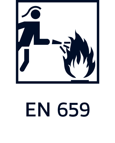
EN 659:2003+A1:2008
PROTECTIVE GLOVES FOR FIREFIGHTERS
This European Standard defines the minimum performance requirements and test methods for firefighters’ protective gloves and applies only to gloves that protect the wearer’s hands during normal firefighting operations (e.g., search and rescue). While these gloves are not intended for the deliberate handling of liquid chemicals, they do provide some protection against accidental contact. Protective gloves designed for specific firefighting operations are excluded from the scope of this standard.
General requirements
Firefighters’ protective gloves must conform to the general requirements of EN 420, excluding minimum glove lengths (see Table 1 below).
If parts of the palm and/or parts of the back of the glove are made from different materials, these materials must be tested separately. In instances where the sample size is significantly larger than the part of the glove being tested, the manufacturer must supply samples of the materials in question. After each thermal test, the material used for the innermost lining must be visually inspected. If there is evidence of melting, the glove will have failed the test.
Table 1
| Glove size | 6 | 7 | 8 | 9 | 10 | 11 |
| Fits | Hand size 6 | Hand size 7 | Hand size 8 | Hand size 9 | Hand size 10 | Hand size 11 |
| Minimum length of glove (mm) | 260 | 270 | 280 | 290 | 305 | 315 |
EN 659:2003+A1:2008 – implies the following performance levels
| Property | Minimum performance level | Norm |
| Abrasion resistance | Level 3 (2000 cycles), palm | EN 388 |
| Cut resistance | Level 2 (index 2,5), palm/back of the hand | EN 388 |
| Tear resistance | Level 3 (50N), palm | EN 388 |
| Puncture resistance | Level 3 (100N), palm | EN 388 |
| Burning resistance | Level 4 After flame time ≤ 2s After glow time ≤ 5s | EN 407 |
| Convection heat resistance | Level 3 (HTI24 ≥ 13), palm/back of the hand | EN367 / EN 407 |
| Radiant heat resistance | RHTI24 at heat flux 40 kW/m2 ≥ 20 sec, back of the hand | EN 6942 |
| Contact heat resistance | At least 10 sec at 250°C, palm (dry/humid environment) | EN 702 |
| Heat resistance of lining | Material must not melt, burst into flames, drop away at temperature of 180°C | ISO 17493 |
| Shrinkage due to heat | Max 5% at a temperature of 180 °C (length/width) | ISO 17493 |
| Dexterity | Level 1 | EN 420 |
| Strength of seams | Min 350 N | EN 13935-2 |
| Time to take the glove off | Max 3 sec (dry/humid environment | EN 15383 |
| Resistance to water penetration | 1-4 = optional test | EN 15383/ EN 20811 |
| Test for intactness of the entire glove | Optional | EN 15383 |
| Resistance to penetration of liquid chemicals | Optional (no chemicals may penetrate for 10s) | EN 6530 |

EN 1082
PROTECTION AGAINST CUTS
Gloves and arm guards protection against cuts and stabs by hand knives.
They are tested at a power of 2.45 joules (falling weight of 1000g at a height of 250mm).
EN 1082-1:1997 Protective clothing – Gloves and arm guards protecting against cuts and stabs by hand knives – Part 1: Chain mail gloves and arm guards
This standard specifies requirements for the design, penetration, resistance, ergonomic characteristics, straps, weight, material, marking and instructions for use, of gloves and arm guards. It also specifies the appropriate test methods. Applies to protective chain mail gloves and to metal and plastics arm guards for use with hand knives.
EN 1082-2:2000 Protective clothing – Gloves and arm guards protecting against cuts and stabs by hand knives – Part 2: Gloves and arm guards made of material other than chain mail
This standard specifies requirements for the design, cut resistance, penetration resistance, and ergonomic characteristics of cut resistant gloves, arm guards and protective sleeves made of materials other than chain mail and rigid metal and plastics, and providing less cut and stab protection than the products specified in part 1 of this standard and are intended to be used only in work where the knife is not finely pointed or it is used only to cut away from the hand and arm.
EN 1082-3:2000 Protective clothing – Gloves and arm guards protecting against cuts and stabs by hand knives – Part 3: Impact cut test for fabric, leather and other materials
This standard contains the specification for an impact cut test for use on fabric, leather and other materials.

EN ISO 10819:2013
MECHANICAL VIBRATION AND SHOCK – HAND-ARM VIBRATION – MEASUREMENT AND EVALUATION OF THE VIBRATION TRANSMISSIBILITY OF GLOVES AT THE PALM OF THE HAND
This International Standard specifies a method for the laboratory measurement, data analysis, and reporting of the vibration transmissibility of gloves with vibration-reducing material that covers the palm, fingers, and thumb.
This standard specifies vibration transmissibility as vibration transmitted from a handle through a glove to the palm in one-third octave frequency bands with center frequencies of 25 Hz to 1 250 Hz. The measurement procedure specified in this standard can also be used to measure the vibration transmissibility of materials being evaluated for use as handle covers for machines or for potential use in glove manufacturing. Results from this test, however, should not be used to certify that a material used as a handle cover will meet this standard’s requirements as they pertain to anti-vibration coverings. While materials tested through this method could be used in glove production, to be classified as an anti-vibration glove, gloves must be tested and certified in accordance with the measurement procedures detailed in this standard (e.g., vibration attenuation performance requirements).
In accordance with ISO 10819, the vibration reduction criteria for an anti-vibration glove are:
TRM < 1.0 (TRM = the overall transmissibility of vibration using a spectrum called “M” [31.5 Hz -200 Hz])
TRH < 0.6 (TRH = the overall transmissibility when using a spectrum called “H” [200 Hz – 1 kHz])
These requirements indicate that in the medium frequency range, an anti-vibration glove must not increase the vibration. In the high frequency range, the glove’s overall effect must be the reduction of the frequency-weighted vibration by at least 40%.
This standard also requires that the resilient, or vibration-damping, material must be placed in the glove’s palm, full finger, and thumb stalls.
Injuries that can occur due to exposure to mechanical vibration and shock are the blanching of fingers, spasms, numbness, and loss of coordination and dexterity. These symptoms are exacerbated by cold temperatures and can last between five and 15 minutes. This increasingly debilitating condition can disable workers and, in extreme cases, result in limb amputation.
To minimize the risk of injuries, specifically the onset of Hand-Arm Vibration Syndrome (HAVS), please consider the following options: lower the vibration exposure action value (EAV) or exposure limit value (ELV); wear anti-vibration gloves; or decrease vibration exposure time by developing more efficient processes or by introducing job rotation.

EN 12477
Protective gloves for welders
This International Standard describes the design specifications for gloves that provide hand and wrist protection for welding and for similar work and should be referred to in conjunction with EN 388 and EN 407. This standard is applicable only in combination with EN 420, excluding that standard’s specifications concerning minimum glove length. Welding gloves must provide protection against mechanical hazards as well as small splashes of molten metal, short contact exposure to limited flame, short exposure to convective heat, against UV radiant heat from arc and against contact heat.
According to their comparative performance levels, protective gloves for welders are divided into two categories:
Type A = gloves that provide a high degree of protection against heat but are less flexible
Type B = gloves that provide a lower degree of protection against heat but are more flexible
Marking conforms to specifications in EN 420 and to the pictograms in EN 388 and EN 407.
Table – Minimum lengths in mm for welding gloves:
| Glove size | 6 | 7 | 8 | 9 | 10 | 11 |
| Fits | Hand size 6 | Hand size 7 | Hand size 8 | Hand size 9 | Hand size 10 | Hand size 11 |
| Minimum length of glove (mm) | 300 | 310 | 320 | 330 | 340 | 350 |
Table – EN 388 minimum mechanical performance levels:
| EN388 | Type A | Type B |
| Abrasion resistance | 2 | 1 |
| Cut resistance | 1 | 1 |
| Tear resistance | 2 | 1 |
| Puncture resistance | 2 | 1 |
Table – EN 407 minimum thermal performance levels:
| EN 407 | Type A | Type B |
| Burning behaviour | 3 (3s / 25s) | 2 (10s / 120s) |
| Contact heat resistance | 1 (100⁰C / 15s) | 1 (100⁰ / 15s)C |
| Convection heat resistance | 2 (7s) | – |
| Drops of molten metal (number of drops) | 3 (25 drops) | 2 (15 drops) |
Lining will be checked after each thermal test and must not melt.
Glove material must not ignite when in contact with drops of molten metal.
ANSI/ISEA 105-2016
ANSI/ ISEA 105-2016 – AMERICAN NATIONAL STANDARD FOR HAND PROTECTION
This standard addresses the classification and testing of hand protection for specific performance properties related to chemical and industrial applications. Hand protection includes gloves, mittens, partial gloves, or other items covering the hand or a portion of the hand that are intended to provide protection against or resistance to a specific hazard. This standard provides performance ranges for related to mechanical protection (cut-resistance, puncture resistance and abrasion resistance), chemical protection (permeation resistance, degradation) and other performance characteristics such as ignition resistance and vibration reductions based on standardized test methods.
Hand protection classifications are subdivided into three main groups:
- Mechanical Protection (cut, abrasion, puncture)
- Chemical Protection
- Other (heat, flame, vibration protection, dexterity, impact protection = ANSI/ISEA 138:2019)
1 – Mechanical protection
Levels of performance:
Cut resistance: levels A1 – A9
Puncture resistance: levels 1 – 5 (Hypodermic Needle puncture)
Abrasion resistance: levels 1 – 6
1/ A1 is the lowest level; 5, 6 and A9 are the highest levels
2 – Chemical Protection
Standard Breakthrough time: levels 1 – 6
1 is the lowest level; 6 is the highest level
3 – Others
Flame and heat resistance
Levels of performance
Flame resistance levels 1 – 4
Heat degradation resistance levels 1 – 4
Conductive heat resistance levels 1 – 5
1 is the lowest level; 4 and 5 are the highest levels
Vibration Reduction
Criteria: TRM <1.0 and TRH < 0.6 levels pass/ fail
Dexterity
Levels of performance: 1 – 5
1 is the lowest level; 5 is the highest level
Impact Resistance (see ANSI/ISEA 138:2019)
Only concerned the knuckle area levels pass/ fail
ASTM D120
Standard Specification for Insulating Gloves Made of Rubber
This standard describes manufacturing and testing processes for insulating gloves made of rubber designed to protect wearers from electrical shock and defines the minimum electrical, chemical, and physical properties of voltage-rated gloves.
ASTM requires gloves to be manufactured within similar hand dimensions, plus or minus ½” per measurement. This allowance provides manufacturers with the opportunity to select a set of unique dimensions.
Two types of gloves are detailed in this standard:
Type I: non-resistant to ozoneType II: resistant to ozone
Six classes of gloves, differentiated by their electrical characteristics, are detailed in this:
Class 00, Class 0, Class 1, Class 2, Class 3, Class 4
The following tests must be performed:
AC proof testAC breakdown testAC moisture absorption/proof testDC proof testDC breakdown testOzone resistance testChemical testsTensile strengthTear resistance testPuncture resistance test
Electrical safety gloves are categorized by their capacity to provide voltage protection and to provide a resistance to ozone. To select the proper level of hand protection, use the chart below to determine the maximum voltage that the wearer will be exposed to during work. Each glove class is clearly marked with the maximum use voltage on the permanent color-coded label.
| Class | Test AC Volts | Use AC Volts | Test DC Volts | Use DC Volts | Label Color |
| 00 | 2500 | 500 | 10000 | 750 | Beige |
| 0 | 5000 | 1000 | 20000 | 1500 | Red |
| 1 | 10000 | 7500 | 40000 | 11250 | White |
| 2 | 20000 | 17000 | 50000 | 25500 | Yellow |
| 3 | 30000 | 26500 | 60000 | 39750 | Green |
| 4 | 40000 | 36000 | 70000 | 54000 | Orange |
Voltage rated gloves should always be purchased with leather protectors and a storage container.
To protect the wearer properly, a glove system consists of:
Rubber insulating gloves – classified by the level of voltage protection they provide.
Liner gloves – reduce the discomfort of insulating gloves made of rubber. Liners provide warmth in cold temperatures and absorb perspiration during work in warmer temperatures. They can have a straight cuff or knitted wrist.
Leather protector gloves – worn over insulating gloves made of rubber to protect against cuts, abrasions, and punctures.
Leather protectors:
In the ASTM standards specifying the characteristics of leather protector gloves, there are regulations concerning how much of the rubber glove can be exposed at the top (i.e., near the cuff.) Due to this, certain leather protector gloves are used with specific classes of rubber gloves according to their length (see below). Note: these protectors are not interchangeable with different classes of rubber gloves.
Class 00 & 0 must have no less than a ½” gap between the top of the glove and the top of the leather protector.Class 1 must have no less than a 1” gap between the top of the glove and the top of the leather protector.Class 2 must have no less than a 2” gap between the top of the glove and the top of the leather protector.Class 3 must have no less than a 3” gap between the top of the glove and the top of the leather protector.Class 4 must have no less than a 4” gap between the top of the glove and the top of the leather protector.
Marking requirements on label:
Size, Manufacturer, ANSI/ASTM standard, Country of origin, Class, Type, Max Use Volt AC/ ColorCuff design, Length
Gloves should be worn within 12 months of their test date to ensure full protection against specified hazards. Unused gloves may be retested and, pending recertification, should be used within 12 months.

LFGB
“Lebensmittel-, Bedarfsgegenstände-und Futtermittelgesetzbuch” (LFBG), or “Foods, Consumer Goods and Foodstuffs Code” is the German Food and Commodities law.
Food contact materials are tested in accordance with the German Food and Daily Necessities Act, Articles 30 and 31 (LFGB and 31, (EU) No 10/2011, 1935/2004/EC).
LFGB food grade testing is based on European Framework Regulation (EC) No. 1935/2004 and EC Directive 76/769/EEC.
EC 1935/2004 states that food contact materials must not threaten human health or bring about changes in food’s composition, smell, and taste.
The directive is supplemented by other directives (and their amendments) related to material groups, including:
- Positive lists of authorised substances
- Special conditions for the use of these substances
- Basic rules for compliance checking
- Overall migration limit of constituents into or onto foodstuffs
- Specific migration limits of certain constituents into or onto foodstuffs
In addition, all food contact materials should be manufactured according to good manufacturing practices (GMP) as regulated by Regulation (EC) 2023/2006.
EC Directive 76/769/EEC (including its amendments) relates to restrictions on the marketing and use of certain dangerous substances and preparations. The directive applies to all articles and materials that come
in contact with foodstuffs.
The “Knife and fork” mark is a symbol of food safety.
Food contact materials that bear the “knife and fork” symbol have passed inspection in accordance with EU food safety regulations agreed to by member states.
LFGB testing is comprised of the following:
- General manufacture and materials
- Sensorial examination: the transfer of smell and taste from products to food
- Plastic migration test and extractable heavy metal test
- Metal composition and extractable heavy metal test
- Material tests to assess the danger of chemical hazards in accordance with Germany’s Chemicals Act.


EN 12568
FOOT AND LEG PROTECTORS: REQUIREMENTS AND TEST METHODS FOR TOECAPS AND PENETRATION-RESISTANT INSERTS
NEN-EN-ISO 12568:2010: This international standard describes the requirements and test methods for toecaps and penetration-resistant inserts
This European Standard specifies the requirements and test methods for toecaps and inserts that provide resistance against mechanical penetration and function as components of PPE footwear (e.g. as described by EN ISO 20345, EN ISO 20346, and EN ISO 20347).
Types of toecaps:
- Internal toecap – a toecap that is incorporated into the footwear and positioned underneath the upper
- External toecap- a toecap that is incorporated into the footwear and positioned on top of the upper
Marking
Toecaps
Toecaps must be clearly and permanently marked with the following information:
a) Toecap size (5 up to and including 10)
b) Left or right
c) Manufacturer’s identification mark
d) Manufacturer’s type designation
e) S or 200 J (for safety toecaps)
P or 100 J (for protective toecaps)
f) The number of this standard
Penetration-resistant inserts
a) Insert size
b) Manufacturer’s identification mark
c) Manufacturer’s type designation
d) The number of this standard
NOTE: embossed marking is acceptable

EN 13832-2:2006
FOOTWEAR PROTECTING AGAINST CHEMICALS – PART 2: REQUIREMENTS FOR FOOTWEAR’S RESISTANCE TO CHEMICALS UNDER LABORATORY CONDITIONS
EN 13832-2: 2006 this standard specifies the requirements for footwear that protects the wearer against specific chemicals. This standard does not apply to footwear with leather outsoles.
Part 2 of EN 13832 affords footwear designers greater flexibility than part 3 by not restricting the choice of material types, save the exclusion of designs with leather outsoles, and by allowing ankle boot styles to be evaluated in testing.
EN 13832-2:2006 details the degradation testing procedure only. Footwear in compliance with this standard resists degradation by at least 2 of the following chemicals:
- B – acetone
- D – dichloromethane
- F – toluene
- G – diethylamine
- H – tetrahydrofuranI
- I – ethyl acetate
- J – n-heptane
- K – 30% sodium hydroxide
- L – 95% sulphuric acid
- M – 65% nitric acid
- N – 99% acetic acid
- O– 25% ammonia solution
- P – 30% hydrogen peroxide solution
- Q – isopropanol
- R – 13% sodium hypochlorite

EN 13832-3:2006
FOOTWEAR PROTECTING AGAINST CHEMICALS – PART 3: REQUIREMENTS FOR FOOTWEAR WITH A HIGH LEVEL OF RESISTANCE TO CHEMICALS UNDER LABORATORY CONDITIONS
EN 13832-3:2006 this standard specifies requirements for all-rubber and all-polymeric footwear designed to provide a high level of resistance to specific chemicals. This footwear resists both degradation (by at least 3 chemicals in the list provided) and permeation (i.e., providing at least Level 1 resistance against 3 of the chemicals listed). This standard specifically excludes leather footwear and low shoe and ankle boot designs.
Part 3 of EN 13832 describes the situations where the wearer is advised to select high-resistance footwear (e.g., when working with especially aggressive chemicals). Unlike part 2, part 3 requires that tests be conducted on footwear’s resistance to chemical permeation and chemical degradation resistance and includes five performance levels.
Performance levels:
Level 1 – 121 to 240 minutes
Level 2 – 241 to 480 minutes
Level 3 – 481 to 1440 minutes
Level 4 – 1441 to 1920 minutes
Level 5 – >1921 minutes
Stated chemicals (at least 3 from the list below):
- B – acetone
- D – dichloromethane
- F – toluene
- G – diethylamine
- H – tetrahydrofuranI
- I – ethyl acetate
- J – n-heptane
- K – 30% sodium hydroxide
- L – 95% sulphuric acid
- M – 65% nitric acid
- N – 99% acetic acid
- O– 25% ammonia solution
- P – 30% hydrogen peroxide solution
- Q – isopropanol
- R – 13% sodium hypochlorite
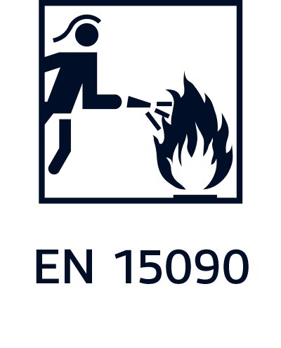
EN 15090:2012
FOOTWEAR FOR FIREFIGHTERS
(EN 15090:2012 supersedes EN 15090:2006.)
EN 15090:2012 specifies the minimum requirements and test methods for the performance of three types of footwear used by firefighters for fire suppression, general-purpose rescue, fire rescue, and emergencies involving hazardous materials. This European standard does not cover the special personal protective equipment (PPE) used in high-risk situations.
Classification:
| Description code | Classification |
| I | Footwear made from leather or other materials, excluding all rubber and all polymeric footwear |
| II | Footwear made entirely of rubber or polymer |
Footwear are classified as:
- Class I: footwear made from leather and other materials, excluding all-rubber or all-polymeric footwear
- Class II: all rubber (i.e. entirely vulcanized), all polymeric (manufactured in one piece), and hybrid footwear (polymeric) footwear with another material that extends the upper
The three types of footwear for firefighters are as follows:
Type 1 Suitable for general-purpose rescue, fire suppression, and firefighting suppression action involving a fire in vegetative fuels such as forests, crops, grass, and farmland; no protection against penetration, no toe protection, and no protection against chemical hazards (these properties however can be present as optional).
Type 2 Suitable for fire rescue, fire suppression, and property conservation in buildings, enclosed structures, vehicles, vessels, or like properties that are involved in a fire or emergency situation; all fire suppression and rescue interventions where toe protection and protection against penetration are needed; no protection against chemical hazards.
Type 3 Emergencies involving hazardous materials, those involving the release or potential release of hazardous chemicals into the environment that can cause loss of life, personnel injury, or damage to property and the environment; suitable also for fire rescue, fire suppression, and property conservation in aircraft, buildings, enclosed structures, vehicles, vessels, or like properties that are involved in a fire or emergency situation; all fire suppression and rescue interventions where toe protection, protection against penetration, and protection against chemical hazards are needed.
Symbols marked on the footwear denote the following features:
| Footwear type | Symbol | Properties |
| Type 1 | F1A | All normative requirements and the requirements for antistatic properties |
| F1PA | All normative requirements and the requirements for penetration resistance for antistatic properties | |
| F1I | All normative requirements and the requirements for electrical insulting properties | |
| Type 2 | F1PI | All normative requirements and the requirements for penetration resistance for electrical insulting properties |
| F2AI | All normative requirements and the requirements for antistatic properties | |
| F2I | All normative requirements and the requirements for electrical insulting properties | |
| Type 3 | F3A | All normative requirements and the requirements for antistatic properties |
| F3I | All normative requirements and the requirements for electrical insulting properties |
Additional symbols that may be marked on the footwear:
| Marking/Symbol | Requirements |
| HI1 | Insulation against heat at 150°C/30 min |
| HI2 | Insulation against heat at 250°C/20 min |
| HI3 | Insulation against heat at 250°C/40 min |
| T | Internal toe cap 200 J (marking only valid for Type 1 boots) |
| R | Rigidity of the toe puff at 500 N (marking only valid for Type 1 boots) |
| P | Penetration resistance |
| I | Electrically insulating footwear |
| A | Antistatic footwear |
| CI | Insulation against cold |
| CH | Chemical resistance |
| AN | Ankle protection |
| M | Metatarsal protection |
Requirements for footwear resistant to slip (slips, trips and falls resistance:
| Marking/Symbol | Test Condition | Mode |
| SRA | Surface: ceramic Lubricant: deteergent solution |
Heel Flat |
| SRB | Surface: smooth steel Lubricant: glycerol |
Heel Flat |
| SRC | SRA + SRB |

EN ISO 20344:2021
Personal protective equipment – Test methods for footwear
EN ISO 20344:2021 supersedes EN ISO 20344:2011.
EN ISO 20344 specifies methods for testing footwear designed as personal protective equipment.
EN ISO 20344 provides test methods necessary to ensure the essential safety requirements, test pieces shall be taken from the whole footwear. These test methods recreate field conditions that shoes might endure in their lifecycle. With the test methods given in EN ISO 20344 you can identify performance and physical aspects of the safety shoes like shock absorption capacity, seam strength, and ankle protection etc.
EN ISO 20344:2021 includes some technical changes with respect to EN ISO 20344:2011. These include:
- For each test same organization (1 principle 2 test equipment’s 3 sampling and conditioning 4 test method 5 test report).
- Systematic inclusion of a clause test report in all the test methods.
- Changes in minimum number of samples and test pieces.
- Several tests are not described anymore in this standard, reference is made to specific standards.
- New standards are taken into account (ISO 17075-1and ISO 17075-2, ISO 22568-1 to ISO 22568-4).
- Conditioning changed from 48 h to 24 h.
- Slip resistance, new test condition.
- Non-metallic perforation resistant insert.
- New drawing for impact test.
- New detection of water resistance.
- New detection of water resistance.
- Clarification in the position and the dimension of the ankle protection.
- New tests for scuff caps.
- New tests for seam strength.
- Determination of the area for non-water vapour permeable material.
- New measurement of cleats height in the waist area.
- New Annexes with new drawings of footwear degradations and with new system of sizing.
The standard will continue to improve and strengthen workplace safety footwear against slips and trips.
Safety shoes approved according to EN 20344:2011 may be sold until the current certificate for the product expires. This means that safety shoes under both norms are permitted until 2027.
EU type certificates have a validity of 5 years.

EN ISO 20345:2022
‘Personal protective equipment – Safety footwear
EN ISO 20345:2022 supersedes EN ISO 20345:2011.
EN ISO 20345 specifies basic and additional (optional) requirements for safety footwear used for general purpose. It includes, for example, mechanical risks, slip resistance, thermal risks, ergonomic behavior. It also specifies requirements for safety footwear equipped with customized in socks, customized safety footwear or individual manufactured customized safety footwear.
This standard does not cover the property of high visibility because of interaction with the clothing (e.g. trousers cover the footwear) and work area conditions (e.g. dirt, mud). Special risks are covered by complementary job-related standards (e.g. footwear for firefighters, electrical insulating footwear, protection against chain saw injuries, protection against chemicals and molten metal splash, protection for motorcycle riders).
It contains a series of changes, ranging from what could be classed as ‘minor’ amendments to ‘major’ alterations. Minor changes may be defined as those that would affect specific materials and/or specific markings, whereas major changes would be amendments which would impact most footwear that has already been tested and certified.
There have been two major changes. The first involves the requirements and testing of slip resistance, and the second affects the penetration resistant inserts for non-metallic materials which changed to perforation-resistant inserts for non-metallic materials, with additional markings.
Changes in test method for slip-resistance:
The test procedures for safety footwear slip-resistance and their corresponding certifications have been changed. The steel plate has been replaced by the ceramic plate for more consistent results.
The test in flat position has been superseded by a forepart position and backward movement.
Previous certifications consisting of ‘SRA’, ‘SRB’ and ‘SRC’ will no longer be used.
In order to obtain the “SR” label, in addition to the anti-slip test on ceramic tiles with a cleaning agent, an additional anti-slip test must be carried out on ceramic tiles with glycerine.
Testing footwear on tile flooring best imitates real-life workplace situations.
The slip resistance basic requirements do not apply to shoes designed for particular purposes,
equipped with spikes, metal studs or similar elements, and intended for very specific
workplaces (soft floors, for example: sand, mud, undergrowth, etc.). In addition, this type of
shoe must be marked with the symbol “ø”.
The following minimum standards must be achieved:
| Marking | Type of surface | Lubricant | Position | Direction | Requirements |
| Basic Requirement
(no marking) |
Ceramic tile | NaLS | Heel | Forward | ≥ 0.31 |
| Forepart | Backward | ≥ 0.36 | |||
| Additional requirement SR | Ceramic tile | Glycerine | Heel | Forward | ≥ 0.19 |
| Forepart | Backward | ≥ 0.22 |
Changes in perforation resistance:
The term penetration resistance for describing safety footwear with inserts as a part of their construction will now be replaced by the phrase perforation resistance.
While only a 4.5mm diameter nail was used in EN ISO 20345:2011, the revised EN ISO 20345:2022 standard offers 3 types of nail protection available.
Testing of steel inserts is carried out with a 4.5mm diameter nail, marked ‘P’.
There are two nail protections available regarding non-metallic inserts: ‘PL’ and ‘PS’. The PL nail has a diameter of 4.5 mm. The PS nail, with a diameter of 3.0 mm, is a new version that companies can test additionally.
Footwear is classified according to the following classes:
- Class I: footwear made from leather and other materials, excluding all-rubber and all-polymeric footwear (S1, S2, S3, S3L and S3S)
- Class II: all-rubber (i.e. entirely vulcanized), all-polymeric (manufactured in one piece), (S4, S5, S5L and S5S)
- Hybrid: SBH = polymeric footwear with another material that extends the upper
| Classification changes (from 5 categories to 7 categories) | ||
| Category | Class I / Class II | Additional requirements |
| SB | Class I / Class II | Basic requirements |
| S1 | Class I | As SB plus:
· Closed heel area · Energy absorption of seat region · Antistatic |
| S2 | Class I | As S1 plus:
· Water penetration and absorption |
| S3 (metal insert type P)
S3L (non-metal insert type PL) S3S (non-metal insert type PS) |
Class I | As S2 plus:
· Perforation resistance according to the type · Cleated outsole |
| S4 | Class II | AS SB plus:
· Closed heel area · Energy absorption of seat region · Antistatic |
| S5 (metal insert type P)
S5L (non-metal insert type PL) S5S (non-metal insert type PS) |
Class II | As S4 plus:
· Perforation resistance according to the type · Cleated outsole |
| S6 | Class I | As S2 plus:
· Water resistance of whole footwear |
| S7 (metal insert type P)
S7L (non-metal insert type PL) S7S (non-metal insert type PS) |
Class I | As S3 plus:
· Water resistance of whole footwear |
| Note 1: For ease of marking, this table categorizes safety footwear with the most widely used combinations of basics and additional requirements | ||
| Note 2: Special-purpose footwear containing spikes, metal studs or similar, designed to enhance performance on soft ground (sand, sludge, forestry timber, etc.) should be marked with ” Ø “. The symbol ” Ø ” indicates that the footwear has not been tested for slip resistance. | ||
| Additional marking codes according to EN ISO 20345:2022 | ||||
| Requirement | Code | Class I/ Class II | Additional information | |
| Perforation resistance (metal insert Type P) | P | Class I/ Class II | 4.5 mm diameter nail | |
| Perforation resistance (non-metal insert Type PL) | PL | Class I/ Class II | 4.5 mm diameter nail | |
| Perforation resistance (non-metal insert Type PS) | PS | Class I/ Class II | 3.0 mm diameter nail (new) | |
| Partially conductive footwear | C | Class I/ Class II | Can only be either partially conductive or antistatic | |
| Antistatic footwear | A | Class I/ Class II | ||
| Heat insulation of outsole complex (footwear with soles resistant to hot environmental conditions) | HI | Class I/ Class II | ||
| Cold insulation of outsole complex | CI | Class I/ Class II | ||
| Energy absorption of seat region | E | Class I/ Class II | ||
| Water resistance | WR | Class I | ||
| Metatarsal protection (requirement related only to safety and protective footwear) | M | Class I/ Class II | ||
| Ankle protection | AN | Class I/ Class II | ||
| Cut resistance | CR | Class I/ Class II | ||
| Scuff cap abrasion | SC | Class I | ||
| Slip resistance (ceramic floor tile with glycerine) | SR | Class I/ Class II | No marking if tested just to 5.3.5.2
SR marked if tested in line with both 5.3.5.2 and 6.2.10 Ø marked if no slip resistance test completed (studded/spiked footwear) |
|
| Water penetration and absorption | WPA | Class I | Upper test | |
| Resistance to hot contact | HRO | Class I/ Class II | Outsole test | |
| Resistance to fuel oil | FO | Class I/ Class II | Outsole test (not mandatory anymore for classes S1 to S5) | |
| Ladder grip | LG | Class I/ Class II | Outsole test (new) | |
| Not tested for slip resistance | Ø | Class I/ Class II | Special-purpose footwear containing spikes, metal studs or similar, designed to enhance performance on soft ground (sand, sludge, forestry timber, etc.) should be marked with “0”. The symbol “0” indicates that the footwear has not been tested for slip resistance. | |
Safety shoes approved according to EN 20345:2011 may be sold until the current certificate for the product expires. This means that safety shoes under both norms are permitted until 2027.
EN 50321:1999
FOOTWEAR FOR ELECTRICAL PROTECTION – INSULATING FOOTWEAR AND OVERBOOTS
EN 50321 pertains to the requirements and testing for electrically insulated footwear and for overboots used for work on live circuits with voltages up to 36,000V AC. The products designed and manufactured according to this standard contribute to the wearer’s safety provided the products are used as intended and in accordance with applicable guidelines. Footwear that is antistatic, shock-resistant, and conductive is not covered by this standard. This standard applies to the following designs: low shoes, ankle boots, half-knee boots, and knee-high boots.
EN 50321:1999 has two classes:
| Electrical Class | Max. nominal AC voltage | Max. nominal DC voltage |
| 00 | 500 V | 750 V |
| 0 | 1.000 V | 1.500 V |
ASTM F2413-11:
STANDARD SPECIFICATION FOR PERFORMANCE REQUIREMENTS FOR PROTECTIVE (SAFETY) TOECAP FOOTWEAR.
ASTM F2413-11 Standard specification for performance requirements for protective (safety) toecap footwear replaces the former ANSI Z41 standard, which was withdrawn in 2005. This specification covers the minimum design, performance, testing, and classification requirements, and prescribes fit, function, and performance criteria for footwear designed to protect against a variety of workplace hazards. It is not the intention of this specification to serve as a detailed manufacturing or purchasing specification. Instead, this specification can be referenced in purchase contracts to ensure that minimum performance requirements are met. Footwear conforming to this specification must meet the performance requirements for the following: impact resistance for the toe area; compression resistance for the toe area; metatarsal protection that reduces the chance of injury to the metatarsal bones at the top of the foot; conductive properties that reduce hazards resulting from static electricity build-up and reduce the possibility of igniting explosives and volatile chemicals; electric shock resistance; static dissipative (SD) properties to reduce hazards caused by exceedingly low footwear resistance that may exist where SD footwear is required; puncture resistance of footwear bottoms; chainsaw cut resistance; and dielectric insulation. The purpose of this standard is to summarize the requirements for certifying protective footwear by independent, third party laboratories.
Footwear certified as meeting ASTM F2413-11 must first meet the requirements of Section 5.1: Impact Resistant Footwear and Section 5.2: Compression Resistant Footwear. Following these assessments, the requirements of additional sections—such as metatarsal protection, conductive protection, electric hazard resistance, static dissipative protection, and protection against punctures—can be met.
All footwear manufactured to the ASTM specification must be marked with the specific portion of the standard with which it complies. One shoe of each pair must be clearly and legibly marked (e.g., stitched in, stamped on, pressure sensitive label, etc.) on either the surface of the tongue, gusset, shaft, or quarter lining. The marking must be enclosed in a rectangular border; a four-line format is recommended. Line four is used only when more than three sections of the standard apply to the footwear.
Each protective toecap must be marked with the manufacturer’s name and trademark or logo. The cap number or identification, toecap size, and R (right)/L (left) designation must be permanently stamped or marked in a conspicuous location. Each metatarsal and puncture-resistant device must be marked with the manufacturer’s name, trademark or logo, and device number or identification in a conspicuous location.
The following is an example of an ASTM F2413-11 marking on protective footwear:
- ASTM F2413-11
- M I/75/C/75
- PR/Mt75
Line 1: ASTM F2413-11
This line identifies the ASTM standard. It indicates that the protective footwear meets the performance requirements of ASTM F2413, issued in 2011.
Line 2: M I/75 C/75
This line identifies the applicable gender [M (Male) or F (Female)] for which the footwear is intended. It also identifies the existence of impact resistance (I), the impact resistance rating (75, 50 or 30 foot-pounds), compression resistance (C), and the compression resistance rating (75, 50, or 30, which correlate to 2500 pounds, 1750 pounds, and 1000 pounds of compression respectively).
Line 3: PR Mt75
Line 3 is used to identify footwear made to protect against the specific hazards described in the standard Cd, EH, SD, PR, Mt. These are used to designate conductive (Cd) properties, electrical hazard resistance properties (EH), footwear designed to reduce the accumulation of excess static electricity (SD), and puncture resistance (PR). The metatarsal designation (Mt) and rating (i.e., 75 foot-pounds) is also identified.
Conductive (Cd) footwear is intended to provide protection for the wearer against hazards resulting from static electricity build-up and to reduce the possibility of igniting explosives and volatile chemicals. The footwear must facilitate electrical conductivity and the transfer of static electricity build-up from the wearer to the ground. The electrical resistance must range between zero and 500,000 ohms.
Electrical hazard (EH) footwear is manufactured with non-conductive, electrical shock-resistant soles and heels. The outsole is intended to provide a secondary source of electric shock-resistance protection for the wearer against the hazards associated with incidental contact with live electrical circuits, electrically-energized conductors, parts, or apparatuses. It must be capable of withstanding the application of 18,000 volts at 60 hertz for one minute with no current flow or leakage current in excess of one milliampere under dry conditions.
Static dissipative (SD) footwear is designed to provide protection against hazards associated with exceedingly low footwear resistance and to maintain a sufficiently high level of resistance to reduce the possibility of electric shock. The footwear must have a lower limit of electrical resistance of 106 ohms and an upper limit of 108 ohms.
Puncture-resistant (PR) footwear features a puncture-resistant plate positioned between the insole and outsole. This plate is an integral and permanent part of the footwear. Devices constructed of metal must pass the ASTM B117-11 Standard Practice for Operating Salt Spray (Fog Apparatus) corrosion resistance testing. The device must show no sign of corrosion after being exposed to a five percent salt solution for 24 hours. The puncture-resistant footwear must show no signs of cracking after being subjected to 1.5 million flexes and have a minimum puncture resistance of 270 pounds.
Metatarsal protection (Mt) footwear is designed to prevent or reduce injuries when the toe and metatarsal areas of the foot are exposed to “drop” hazards.
Any changes to the original components of safety toe footwear, such as replacing or adding foot beds or inserts, could cause failure to any or all parts of the ASTM standard invalidates the safety marking.


EN 136:1998
RESPIRATORY PROTECTIVE DEVICES – FULL FACE MASKS
This standard specifies the minimum requirements for full face mask respiratory protective devices. Full face masks for diving apparatuses are not included in the scope of this standard. Laboratory and practical performance tests are included in these requirements’ compliance assessments. A mask is a full face piece that covers the eyes, nose, mouth, and chin and that provides the wearer with respiratory protection in the form of an appropriate seal against specific atmospheric conditions and airborne hazards. Respirators and masks are manufactured in natural rubber, EPDM, and silicone and are available in designs and with filters that conform to a variety of safety standards (e.g., EN 141, EN 143, and EN 371).
This standard covers three types of full-face masks, all provide the same level of respiratory protection but have differences in terms of their applications:
- CL 1: Full mask for light duty
- CL 2: Full mask general use
- CL 3: Full mask for special use
Requirements include temperature stability, impermeability, and concentration of carbon monoxide, breathing resistance, speech diaphragms, and field of vision.
Requirements:
- Materials
- Resistance to temperature
- Inflammability
- Resistance to thermal radiation
- Finished pieces
- Replaceable components
- Headband
- Connectors
- Speech diaphragm
- Eye and viewers
- Inhalation valves and exhalation valves
- Air tightness
- Skin compatibility
- Carbon dioxide content in the air inhaled
- Breathing resistance
- Inward leakage
- Field of View
Marking package:
- Manufacturer
- Type and Class
- Standard
- CE marking
- Reference to user instructions
- Size notation (if more sizes are available)
- Country of origin
Marking on face mask:
- Manufacturer
- Type and Class
- Standard
- CE marking
- Size notation (if more sizes are available)
- Country of origin
- Production year (clock notation)
- The marking signs need to be clear and durable

EN 140
RESPIRATORY PROTECTIVE DEVICES – HALF MASKS AND QUARTER MASKS
This standard specifies the minimum requirements for half- and quarter masks for use as part of respiratory protective devices. Requirements include testing inward leakage, breathability, flammability, and the mechanical tightness of valves and connections. These facepieces can be used in negative pressure isolation chambers and powered or supplied air systems. If used in a negative pressure isolation chamber, the mask should have filters conforming to EN 141, EN 143, EN 371 or EN 372 attached to it. Please note that the requirements of this standard do not apply to escape- and diving apparatuses.
Half or quarter masks: masks that cover the nose, mouth, and chin or the nose and mouth only. The facepiece is generally made of flexible rubber or silicone and can be fitted with a range of replaceable filters that conform with the requirements specified in EN 141, EN 143, EN 371, and EN 372. Since heavy filters are uncomfortable and compromise the strength and protective capacities of face seals, the maximum weight of filters that are to be fitted to half masks is 300g. Half masks should be fitted in accordance with the EN 148/1 standard specifying thread fitting.

EN 143:2021
Respiratory protective devices – Particle filters
EN 143:2021 supersedes EN 143:2000 Corrected 2002, 2006, Amended 2006
EN 143:2021 specifies particle filters for use as replaceable components in unassisted respiratory protective devices (RPD) with the exception of escape devices and filtering face pieces. Laboratory tests are included for the assessment of compliance with the requirements. Some filters complying with this standard can also be suitable for use with other types of respiratory protective devices and/or escape devices. If so, they need to be tested and marked according to the appropriate European Standard. This standard does not cover requirements concerning respiratory hygiene. Requirements for decrease of the microbiological hazards caused by the growth of bacteria and viruses on the filtration material are not determined.
The following main technical changes have been made compared to EN 143:2000:
- a) Definitions and symbols added;
- b) Description deleted;
- c) Nominal values and tolerances changed;
- d) Use of a risk assessment, e.g. a Failure Modes and Effect Analysis (FMEA) added;
- e) Twin filters added;
- f) Clogging deleted;
- g) Visual inspection changed to inspection and detailed list inserted;
- h) Filter penetration test changed to refer to EN 13274-7;
- i) Marking changed to filters in general;
- j) All figures adapted to the changes made in the test procedures, where appropriate.
Based on their efficiency, particle filters are divided into three categories:
- P1 – low filtration, intended for use against solid particles only
- P2 – medium filtration, subdivided according to the filters’ capacity to remove both solid and liquid particles or solid particles only
- P3 – high filtration, subdivided according to the filters’ capacity to remove both solid and liquid particles or solid particles only
| Class | Filter penetration limit (at 95 L/min air flow) |
| P1 | Filters at least 80% of airborne particles |
| P2 | Filters at least 94% of airborne particles |
| P3 | Filters at least 99.95% of airborne particles |
Markings:
P + particle category
R (= reusable), or NR (= not reusable /single shift)
CE marking with approval number of notified body
Color code: white
Additional markings:
- Whether the filter is intended for use in a multi-filter device
- Indication (+ expired hourglass symbol) of filter’s expiration date, formatted as “yyyy/mm”

EN 148-1
RESPIRATORY PROTECTIVE DEVICES – THREADS FOR FACEPIECES – PART 1: STANDARD THREAD CONNECTION
This European Standard is applicable to standard threads for respiratory protective devices. This standard describes the different connection types between the PPE and filters in regards to the masks. The most common standard is EN 148-1 which is described by thread Rd40 x 1/7”. This standard does not apply to diving equipment and to positive pressure breathing apparatus.

EN 149
RESPIRATORY PROTECTIVE DEVICES – FILTERING HALF MASKS TO PROTECT AGAINST PARTICLES – REQUIREMENTS, TESTING, MARKING
This European Standard specifies the minimum requirements for filtering half masks used as respiratory protective devices, specifically against particles, and the required laboratory and practical performance tests to assess masks’ compliance. Half masks used for escape purposes are excluded from the scope of this standard.
A filtering half mask is one in which the facepiece consists entirely or substantially of filter material or comprises a facepiece in which the main filter(s) form an inseparable part of the device.
Under the preceding EN149:1991 standard, the classifications were FFP1S, FFP2S, FFP2SL, FFP3S and FFP3SL. EN149:2001 classified half masks into three types according to their filtering capacities (e.g., FFP1, FFP2, and FFP3). Respirators that meet the requirements of EN149:2001 are designed to protect against solids, water-based aerosols, and oil-based aerosols.
EN149:2001 differs from EN149:1991 in that it is mandatory for all products tested in accordance with EN149:2001 to provide protection against solid and liquid aerosols whereas EN149:1991 allows for the testing of respirators against solid aerosols only. On 1 August 1 2010, an amendment to EN 149.2001 standard entered into force concerning the reusability of masks’ dust filters, indicated by “R”, reusable, and “NR”, non reusable, and tagged as EN 149:2001+A1:2009.
EN 149 defines the following classes of filtering half masks (i.e., respirators that are entirely or substantially constructed of filtering material):
Class APF (Assigned Protection factor) Filter penetration limit (at 95 L/min air flow) Inward leakage
| Class | APF (Assigned Protection factor) | Filter penetration limit (at 95 L/min air flow) | Inward leakage |
| FFP1 | 4 | Filters at least 80% of airborne particles | <22% |
| FFP2 | 10 | Filters at least 94% of airborne particles | <8% |
| FFP3 | 20 | Filters at least 98% of airborne particles | <2% |
To confirm: an FFP3 respirator mask would filter out at least 98% of the airborne respirable particles, whereas an FFP1 respirator mask would filter out at least 80% of the respirable particles. FFP3 respirator masks are, therefore, the most efficient in filtering out fine particles including viruses, mold spores, and asbestos.

EN 166:2001
PERSONAL EYE PROTECTION – SPECIFICATIONS
This standard specifies the functional requirements for various types of personal eye protectors, incorporates general considerations concerning designation, classification, universal requirements for eye protection, testing and application, and safety marking, and describes how both frames and lenses are to be tested.
EN 166 is the core technical standard that all PPE used to protect the eyes or face must be approved in accordance with. Depending on equipment’s intended use, protection requirements may differ.
Marking on lens/oculars must include:
- The scale number for filtering lenses/radiation protection:
2 – UV Protection (EN 170): “2” indicates that the filter may affect colour recognition.
2C or 3 – UV Protection (EN 170): “2C” (previously “3”) indicates that the filter allows good colour recognition.
4 – Infrared (IR) Protection (EN 171): protection from heat.
5 – Solar Protection (EN 172): 100% UV sun glare protection with no IR protection.
6 – Solar Protection (EN 172): 100% UV sun glare protection with IR protection.
- The manufacturer’s name (note: logo or brand recommended by the manufacturer).
- Optical class symbols, ranked according to effectiveness:
Class 1 – Continuous work: suitable for occasional wear (refractive power of ± 0.06 dioptres).
Class 2 – Intermittent work: suitable for occasional wear (refractive power of ± 0.12 dioptres).
Class 3 – Occasional work: suitable for exceptional wear (refractive power of ± 0.25 dioptres).
- Field(s) of use symbols:
3 – Liquids droplets (goggles) or liquid splashes (face shields, but not those made of mesh)
4 – Large dust particles (i.e., particles size >5μm)
5 – Gases and fine dust particles (e.g., particle size <5μm)
8 – Protection against short circuit/electric arc
9 – Molten metal and hot solids
- Optional requirements:
K – Hard coat: resistance to surface damage by fine particles (optional); anti-scratch protection
N – Non-mist: resistance to misting/fogging (optional)
R – Enhanced reflectance (optional)
G – Radiant heat: mesh-type protection only
H – Eye protector designed to fit small-sized heads/faces
- Mechanical strength symbols:
None – without mechanical strength (i.e., filters only)
S – Extra strong: resists a 22 mm, 43 g ball falling 1.30 m at 5.1 m/s (oculars only)
F – Low energy impact: resists a 6 mm, 0.86 g ball falling 1.30 m at 45 m/s (any type)
B – Medium energy impact: resists a 6 mm, 0.86 g ball falling 1.30 m at 120 m/s (goggles and face shields only)
A – High-energy impact: resists a 6 mm, 0.86 g ball falling 1.30 m at 190 m/s (face shields only)
T – The letter T: indicates protection against high-speed particles heated to extreme temperatures if written following a mechanical strength symbol (e.g., F, B or A).
- Certification mark (CE)
Note: a combination of the symbols and numbers mentioned above is possible.
Marking on the frame must include:
- The manufacturer’s name (logo or brand recommended by the manufacturer)
- Number of the EN Standard
- Field(s) of use symbols:
3 – Liquids droplets (goggles) or liquid splashes (face shields, but not those made of mesh)
4 – Large dust particles (i.e., particles size >5μm)
5 – Gases and fine dust particles (e.g., particle size <5μm)
8 – Protection against short circuit/electric Arc (face shields only)
9 – Molten metal and hot solids (note: goggles and face shields only)
- Optional requirements:
K – Hard coat: resistance to surface damage by fine particles (optional); anti-scratch protection
N – Non-mist: resistance to misting/fogging (optional)
R – Enhanced reflectance (optional)
G – Radiant heat: mesh-type protection only
H – Eye protector designed to fit small-sized heads/faces
- Mechanical strength symbols:
None – without mechanical strength (i.e., filters only)
S – Extra strong: resists a 22 mm, 43 g ball falling 1.30 m at 5.1 m/s (oculars only)
F – Low energy impact: resists a 6 mm, 0.86 g ball falling 1.30 m at 45 m/s (any type)
B – Medium energy impact: resists a 6 mm, 0.86 g ball falling 1.30 m at 120 m/s (goggles and face shields only)
A – High-energy impact: resists a 6 mm, 0.86 g ball falling 1.30 m at 190 m/s (face shields only)
T – The letter T: indicates protection against high-speed particles heated to extreme temperatures if written following a mechanical strength symbol (e.g., F, B or A).
- Certification mark (CE)
Note: a combination of the symbols and numbers mentioned above is possible.
Scale Number – for lenses with filtering effect only.
The scale number is a code number and a shade number separated by a hyphen (note: welding filters have no code number). Higher shade numbers indicate a stronger filtering effect (e.g. they are darker for welding). Example: an IR filter with shade number 4 has the scale number 4-4.
| Welding filters (See EN 169 and EN 379) | No code number; shade number between 1.2 and 16; suffix denotes filter for use in gas welding with flux |
| UV filters (See EN 170) | 2C- or 3- – code number denoting UV filter without or with good colour recognition, respectively; shade number between 1.2 and 5 |
| IR filters (Infra-red) (See EN 171) | 4- – code number for IR filters; shade number between 1.2 and 10 |
| Sun glare (See EN 172 and EN 1836) | 5- code number for sun glare filters without IR specification; shade number between 1.1 and 4.1 |
| Sun glare (See EN 172 and EN 1836) | 6- – code number for sun glare filters with IR specification; shade number between 1.1 and 4.1 |
| Shade number | Typical lens colour | VLT range |
| 1.2 | Clear | 100% – 74.4% |
| 1.7 | In/Out, yellow, clear mirrored, UVR | 58.1% – 43.2% |
| 2.5 | Brown, smoke | 29.1% – 17.8% |
| 3.1 | G15, smoke mirrored | 17.8% – 8.0% |
| 3,4,5,…11 | Welding | – |

EN 169
PERSONAL EYE PROTECTION – FILTERS FOR WELDING AND RELATED APPLICATIONS – TRANSMITTANCE REQUIREMENTS AND RECOMMENDED USE
This standard specifies the scale numbers and transmittance requirements for filters intended to protect operators performing work involving welding, braze-welding, air-arc gouging, and plasma jet cutting. It also includes requirements for welding filters with dual scale numbers. The other applicable requirements for these types of filters are detailed in EN 166. The requirements for fitting frames and mountings are described in Annex EN 175.
The numbering table for filters and the reference for marking oculars and frames are available in EN 166.

EN 170:2002
PERSONAL EYE PROTECTION – ULTRAVIOLET FILTERS – TRANSMITTANCE REQUIREMENTS AND RECOMMENDED USE
This European Standard specifies the scale numbers and transmittance requirements for filters that protect against ultraviolet (UV) radiation. Other applicable requirements for these types of filters, along with the frames and mountings to which these filters are affixed, are available in EN 166. Guidance concerning the selection and use of these filters is available in Annex B.
Note: the protective filters that serve as examples in this standard are not suitable for the direct viewing of bright light (e.g., from sources such as Xenon high-pressure arc lamps) nor are they suitable for the direct and indirect observation of an electric welding arc.
The numbering table for filters and the reference for marking oculars and frames are available in EN 166.

EN 172:1995
PERSONAL EYE PROTECTION – SUNLIGHT FILTERS FOR INDUSTRIAL USE
This standard specifies the scale numbers, transmittances, and related requirements for sun glare filters designed for industrial use. Other requirements for these types of filters are specified in EN 166. Section criteria and information pertaining to the use of these filters are available in Annex A. This standard does not apply to filters that protect against radiation from artificial sources, such as those used in solaria, nor does it apply to ski goggles. To confirm: a separate standard is forthcoming for sunglasses and sun glare filters intended for general use.
The numbering table for filters and the reference for marking oculars and frames are available in EN 166.

EN 175
PERSONAL PROTECTION – EQUIPMENT PROVIDING EYE AND FACE PROTECTION FOR WELDING AND RELATED PROCESSES
This standard specifies the safety requirements and test methods for personal protective equipment (PPE) that protects the wearer’s eyes and face against harmful optical radiation and other specific risks and hazards associated with welding, cutting, or similar operations (e.g., ergonomic, fire, mechanical, and electrical). The resulting equipment is designed to incorporate protective filters, with or without cover/backing oculars, as recommended by the welding protector manufacturer and in accordance with EN 166:1995 and in compliance with EN 169:1992 or EN 379:1994.
Hoods, inspector face screens, laser protective equipment, and welding protection for special applications, are beyond the scope of this standard.
Additionally, this standard defines the terms used and specifies requirements for product designs, materials, and manufacturing processes.
The numbering table for filters and the reference for marking oculars and frames are available in EN 166.
EN 352-1:2020
Hearing protectors – General requirements – Part 1: Earmuffs
EN 352 standards explained:
The first 3 parts of EN 352 cover the basic requirements of hearing protection and define the passive performance requirements.
To meet the EN352 standards, hearing protection is tested in the following areas (subject to product type):
- Materials and construction
- Sizing and adjustability
- Cup rotation
- Headband force
- Cushion pressure
- Resistance to damage when dropped
- Change in headband force
- Resistance to leakage
- Ignitability
- Minimum attenuation
- Marking
- Information supplied by the manufacturer
EN 352-1:2020 supersedes EN 352-1:2002.
EN 352-1:2020, the first section of the EN 352 standard, specifies requirements for construction, design, performance, marking and user information for earmuffs.
Ear-Muffs: Two ear cups that are filled with sound absorbing foam. Each cup has a soft pad that is either foam or foam and liquid filled. The ear cups are held in place with a tensioned neckband or headband.
In particular, the standard specifies requirements regarding the sound attenuation of the earmuffs, measured in accordance with EN ISO 4869-1:2018.
The Standard does not apply to earmuffs outside the size range of head sizes as defined in this Standard.
The Standard does not apply to earmuffs for attachment to head protection and/or face protection devices.
Ergonomic aspects are addressed by taking into account, within the requirements, the interaction between the user, the device and where possible the working environment in which the device is likely to be used (see Annex ZA and EN 458 in standard).
For industrial applications, the Control of Noise at Work Regulations 2005 came into force in 2006 which reduced the starting point for ear protection from 85 dB to 80 dB. Workers must be informed and provided with training when noise levels reach 80 dB (was 85 dB) and protection should be made available. Protection must be provided by the employer when sound levels reach 85 dB or above.
SNR (Single number rating)
This is the number of potential decibels the hearing protection will reduce the noise when correctly fitted.
The objective is to select a suitable product that reduces the wearer’s noise level down to between 70 dB & 80 dB.
To reduce the noise level to below 70 dB may impair the wearer from hearing any alarm or warning sounds.
HML (relates to frequency)
H=High. M=Medium. L=Low. This relates to how the product performs
within these general frequency bands. The values of each of these
(attenuation levels) will be located on the product packaging. Note that a
SNR of 27 will not necessarily be attributable to all frequency levels – this
should be considered when selecting a product for a specific frequency.
In accordance with EN 352, all hearing protectors must be marked with:
- Manufacturer’s name or trademark and model name
- EN number
- Instructions on insertion, application and wearing (as necessary)
- Nominal size
- CE marking
- Indication of reusability or single use (relevant for earplugs)
- Left or right marking (for otoplastics)
EN 352-2:2020
Hearing protectors – General requirements – Part 2: Earplugs
EN 352-2:2020 supersedes EN 352‑2:2002, which is withdrawn.
EN 352-2:2020, the second section of the EN 352 standards, specifies the constructional, design, performance and marking requirements for EN 352 compliant earplugs.
In particular, it specifies requirements regarding the sound attenuation of the earplugs, measured in accordance with EN ISO 4869-1:2018.
This document applies to earplugs designed for users who are able to follow supplied instructions and understand the related risks, can fit the earplugs correctly and can give feedback on the performance.
Ergonomic aspects are addressed by taking into account, within the requirements, the interaction between the user, the device and where possible the working environment in which the device is likely to be used (see Annex ZA and EN 458).
EN 352-2 defines earplugs as all hearing protectors that are worn directly in the auditory canal or ear cavity.
There are three main types of earplugs (i.e. pre-moulded earplugs, individually moulded earplugs and adaptable earplugs). Pre-moulded earplugs are moulded to fit the ear canal. They are available in disposable and re-useable types and come in foam or PVC material.
According to the regulations, use of earplugs is recommended:
- For continuous noise (lower frequencies)
- When earmuffs tend to cause strong sweating
- When also wearing safety spectacles
- When wearing other protective equipment such as head protection or face protection
- Together with earmuffs for brief periods of extreme noise
In accordance with EN 352, all hearing protectors must be marked with:
- Manufacturer’s name or trademark and model name
- EN number
- Instruction on insertion, application and wearing (as necessary)
- Nominal size (of formable plugs, in range 5 to 14 mm)
- CE marking
- Indication of reusability or single use (relevant for earplugs)
- Left or right marking (for otoplastics)
The markings for EN 352-2 may only appear on the packaging.

EN 352-3:2020
Hearing protectors – General requirements – Part 3: Earmuffs attached to head protection and/or face protection devices
EN 352-3:2020 supersedes EN 352-3:2002, which is withdrawn.
EN 352-3:2020, the third section of the EN 352 standard, specifies requirements for construction, design, performance, marking and user information for earmuffs attached to head protection and/or face protection devices, hereinafter referred to as ‘mounted earmuffs.
It specifies requirements regarding the sound attenuation of mounted earmuffs, measured in accordance with EN ISO 4869-2:2018.
The Standard does not apply to earmuffs outside the size range of head sizes as defined in this standard.
Because one model of earmuffs designed to be attached to head protection and/or face protection devices can be fitted to a number of other models and sizes of the carrier, this part of the standard sets out a series of physical and acoustic requirements for earmuffs when fitted to the specified model(s) or size(s) of head protection and/or face protection device.
All requirements apply to earmuffs fitted to one of the specified models or sizes of head protection and/or face protection device (the basic combination). An abbreviated set of requirements applies to the same model of earmuffs when fitted to the other specified models or sizes of head protection and/or face protection device (the supplementary combinations).
Ergonomic aspects are addressed by taking into account, within the requirements, the interaction between the user, the device and, where possible, the working environment in which the device is likely to be used (see Annex ZA and EN 458).
Marking ear muffs:
- Manufacturer/company name
- Identification or model number
- Number and date of the standard
- When required- e.g. “Top “and/or “Left “and “Right”
EN 353-1
PERSONAL PROTECTION AGAINST FALLS – PART 1: GUIDED TYPE FALL ARRESTERS WITH RIGID ANCHOR LINES
EN 353-1:2002 specifies the requirements, test methods, marking, manufacturer information, and packaging for guided type fall arresters that include rigid anchor lines (i.e., those commonly attached to or integrated in fixed ladders or on rungs that are adequately adjusted to suitable structures). Guided type fall arresters with rigid anchor lines that conform with this European standard are sub-systems constituting one of the fall arrest systems covered by EN 363 only when combined with a full body harness that includes a front attachment point located in proper relation to the fall arrester (see EN 361). Other types of fall arresters are described in EN 353-2 and EN 360. Energy absorbers are detailed in EN 355.
This standard has been withdrawn due to the occurrence of fall protection accidents for which proper reporting concerning causes is unavailable. Even as fall arresters meet the applicable safety standard (i.e., EN 353-1), it has not been possible to prevent these accidents. The withdrawal of EN 353-1:2002 indicates that meeting the requirements specified in EN 353-1:2002 does not establish sufficient protection.
EN 353-1:2014 supersedes BS EN 353-1: 2002. Annex B (informative) lists the significant technical changes between the new and preceding versions of the standard.
EN 353-1:2014 specifies the requirements, test methods, marking, manufacturer information, and packaging for guided type fall arresters that include rigid anchor lines (i.e., those commonly attached to or integrated in fixed ladders or on rungs that are adequately adjusted to suitable structures). Guided type fall arresters with rigid anchor lines that conform with this European standard are sub-systems constituting one of the fall arrest systems covered by EN 363 only when combined with a full body harness that includes a front attachment point located in proper relation to the fall arrester (see EN 361). This European standard applies to rigid anchor lines installed vertically and/or with a combination of a forward-leaning angle and/or a lateral angle between the true vertical and the vertical +15°. Multi-user applications (i.e. rigid anchor lines that allow more than one user to be attached at any one time) are not addressed in this document.
Summary of key changes:
Angled systems:
Previously, the standard covered only systems in the vertical position. The revised standard covers systems between the vertical and the vertical +15°.
Minimum and maximum loads:
Guided type fall arresters must now be tested with both a minimum and maximum loads and should be marked accordingly. Previously, the standard required testing with a load of 100 kg.
Permanent attachment:
Connecting elements are now required to be permanently attached to the guided type fall arrester.
User intervention:
When attached to the rigid anchor, guided type fall arresters are must accompany the user upward and downward without manual intervention.
U-bolt clamps:
Top terminations to the rigid anchor lines using U-bolt clamps are no longer acceptable.
Functionality:
By outlining tests that must be undertaken, the standard now places greater emphasis on the functionality of the rigid anchor line and the guided type fall arresters. These function tests measure performance in low temperatures, at minimum distances, during fall backs, when affixed to a guiding bracket, during sideways falls, and the strength of sideways-leaning anchors.
EN 353-2:2002
PERSONAL PROTECTION AGAINST FALLS – PART 2: GUIDED TYPE FALL ARRESTERS WITH FLEXIBLE ANCHOR LINES
EN 353-2:2002 specifies the requirements, test methods, marking, manufacturer information, and packaging for guided type fall arresters that include flexible anchor lines (e.g., those that can be secured to an upper anchor point). Guided type fall arresters with include flexible anchor lines in conformance with this European standard are subsystems constituting one of the fall arrest systems covered by EN 363. Other types of fall arresters are described in EN 353-1 or EN 360. Energy absorbers are detailed in EN 355.
EN 353-2
Guided type fall arresters (flexible lines)
These are systems comprised of a fixed line, either temporary or permanent, on which a travelling device is attached. The user connects to this travelling device when climbing or descending. In the event of a fall, the travelling device should grip the line and stop the fall.
Dynamic Performance
Guided type fall arresters are subject to a drop test using a 100 kg mass, released over the maximum distance the device will allow (e.g., by raising the mass until the travelling device begins to slide up the cable or rail). The device should not deploy more—by movement of the travelling device, stretching the rope, or through deployment of energy absorbing elements—than 1 meter and with a maximum arrest force of 6 kN.
Locking after Conditioning
With mechanical devices, additional testing is required to ensure they are not adversely affected by environmental conditions. Devices’ locking function can be tested with a mass of at least 5 kg after the devices have been exposed to 50°C with 85% relative humidity for at least 2 hours, to -30°C for at least 2 hours, and to water sprayed in volumes of 70 liters/per hour for at least 3 hours. Optional testing would follow devices’ submersion in diesel oil or dust.
Static Strength
Whole products are subjected to tensile tests. Textile lanyards are subject to a 15 kN tensile force and metal lanyards to 12 kN. Tensile forces are applied and held for at least 3 minutes to ensure that the products’ breaking strengths of the products exceed the force specified by the standard.
Corrosion Resistance
Metallic components used in fall protection equipment are subjected to a neutral salt spray test designed to determine products’ capacity to resist environmental corrosion and rusting. Products are exposed to saltwater mist for 24 hours inside a sealed chamber. Following this exposure, products are examined for signs of rusting and diminished functionality.

EN 354
PERSONAL FALL PROTECTION EQUIPMENT – LANYARDS
EN 354:2010 supersedes EN 354:2002 and specifies the requirements, test methods, marking, manufacturer information, and packaging for lanyards. Lanyards conforming to this European standard are used as connectors and components in personal fall protection systems (e.g., restraint systems, work positioning systems, rope access systems, fall arrest systems, and rescue systems).
Lanyards are a standard component in the fall protection systems for those working at height, with a variety of designs, lengths, materials, and configurations. Since lanyards are exposed to intense wear and tear during use, rigorous testing of their protective capacities is imperative. This updated standard increases the amount of testing required to ensure that CE-marked lanyards provide appropriate protection against these worksite hazards.
Summary of key changes:
Design
The requirement in EN 354:2002 that lanyards measure 2m (at maximum) has been eliminated, meaning lanyards longer than 2m now fall under the scope of this standard. The only design requirement is that lanyards must be marked with their lengths (±5%).
Testing conditions
Specific conditioning requirements have been added. Test samples must be conditioned at 23oC (±5oC) and 65% (±5%) relative humidity (rh) for at least 24 hours prior to testing.
Additionally, “wet and cold” and “very cold” conditions have been added. Lanyards tested in accordance with EN 354:2010 must be subjected to “wet and cold” conditions; subjecting lanyards to the “very cold” condition is optional but recommended for lanyards intended for use in temperatures to as low as -30oC.
Slippage
EN 354:2010 includes an adjustable lanyard slippage test (see the related test in EN 358:1999). To pass this test, the adjustment device must not slip more than 50mm. The assignation of a “very cold” performance rating requires that the slippage test be repeated after the test samples have been subjected to “very cold” conditioning.
Static strength
The standard retains the 2002 edition’s 22kN static strength requirement for textile. Lanyards constructed entirely from metal are subjected to a 15kN static strength test, as they are more resilient to wear and tear. Test methods for twin-tail lanyards are now included. Any multi-leg lanyard must be tested in all possible configurations and to a force of either 22kN (textile) or 15kN (metal). Each configuration should be tested in relevant conditions.
Dynamic
Lanyards that include a length adjustment device must be subjected to a dynamic strength test. This test differs from previous tests for adjustable lanyards. A 100kg test mass must be attached to the test sample through a standard 2m lanyard. The mass is raised 2m above the attachment point, creating a free-fall distance of 4m. To pass this test, the lanyard must prevent the test mass from touching the ground. Note: measuring the forces generated is not required.
Following the dynamic test, the adjustment device must be subjected to a 3kN static strength test to determine the lanyard’s residual strength. If the lanyard can withstand this force for 3 minutes after the mass is dropped, the lanyard will have met the standard’s requirements.
Corrosion
Metallic components’ susceptibility to corrosion is now assessed following a 48-hour exposure time (note: in the preceding standard, the exposure time was 24 hours). Increased exposure to the neutral salt spray can lead to the failure of metallic components used in products that were tested against the 24-hour exposure time requirement. It is likely that a lengthier exposure time will result in the use of stronger coatings on lanyards’ metal components.
Product marking
Product markings must indicate the lanyard’s length and its date of manufacture. Information regarding the pictogram, model/type, and marking has been moved to EN 365.

EN 355:
PERSONAL PROTECTIVE EQUIPMENT AGAINST FALLS FROM A HEIGHT – ENERGY ABSORBERS
EN 355:2002 describes the requirements, test methods, marking, manufacturer information, and packaging specifications for energy absorbers. Energy absorbers in conformance with this European Standard are components of, or used in combination with, lanyards, anchor lines, and full body harnesses. The combination of an energy absorber and a lanyard constitutes one of the fall arrest systems detailed in EN 363 and, when combined with a full body harness, among those systems described in EN 361. In addition, EN 353-1, EN 353-2, and EN 360 pertain to fall arrest devices.
If a user falls while connected to a 2m long textile lanyard without an energy absorber, the force on the user and the anchor would be unacceptably high. Therefore, every fall arrest system must be equipped with an energy absorber to limit the impact force to 6kN.
EN 355:2002
Shock absorbing lanyards
Lanyards intended for use in connecting the attachment point of a full body harness to a secure anchorage device must include a shock-absorbing component that reduces the force applied to the wearer by gradually arresting their fall. In the event of a fall, shock absorbers should limit the impact force to a maximum of 6kN.
Dynamic Performance
Shock absorbing lanyards are subject to a drop test to assess the lanyard’s capacity to arrest a fall within a maximum distance while limiting the arrest force to an acceptable range. The lanyard should not deploy (i.e., stretch, open, tear) beyond a maximum length of 1.75m, with a maximum force of 6 kN, when supporting a 100kg solid mass released over a distance that is twice the lanyard’s length. Energy absorbers that are sold separately (e.g., as components) must be extended with a chain to a length of 2m and tested using a mass released over a distance of 4m.
Static Strength
Energy absorbers are subjected to a 15 kN tensile force. Tensile forces are applied and held for at least 3 minutes to ensure that the product’s breaking strength exceeds the force specified in the standard.
Corrosion Resistance
Metallic components used in fall protection equipment are subjected to a neutral salt spray test to determine whether the product can provide a minimum resistance to environmental corrosion (e.g., rust). Products are held in a sealed chamber filled with a saltwater mist, which can cause untreated metals to rust. Products are subjected to either 24 or 48 hours of exposure and examined thereafter for signs of rust and to assess whether each device can continue to function properly.

EN 358:
PERSONAL PROTECTIVE EQUIPMENT FOR WORK POSITIONING AND PREVENTION OF FALLS FROM A HEIGHT – BELTS AND LANYARDS FOR WORK POSITIONING AND RESTRAINT
EN 358:2015 supersedes EN 358:2000 and applies to belts and lanyards designed for work positioning and restraint. It specifies the requirements, testing, marking, manufacturer information, and packaging specifications that must be supplied by manufacturers. The standard does not pertain to restraint lanyards with fixed lengths integrated into belts.
The waist strap must be no less than 43 mm wide and the back support no less than 100 mm wide. Lanyards can be equipped with adjustable shoulder and sitting straps but, for normal use, must include a length adjuster and with a maximum length of 2 m.
Clear instructions for fitting, adjustment, and use must be supplied with each belt. Markings must indicate applicable standards, the manufacturer’s name, and the product’s serial number. The year and month of manufacture should be included in or on the product packaging.
Belts and lanyards tested in accordance with EN 358 must be used only for work positioning and restraint, allowing for hands-free movement. These items must not be used as a part of, or incorporated in, a fall arrest system.
In accordance with EN358, an accredited examiner must recertify fall arrest, work positioning harnesses every 12 months (at maximum).
EN 360:
PERSONAL PROTECTIVE EQUIPMENT AGAINST FALLS FROM A HEIGHT – RETRACTABLE-TYPE FALL ARRESTERS.
This European Standard describes the requirements, test methods, marking, manufacturer information, and packaging specifications for retractable-type fall arresters. Retractable-type fall arresters that conform to this standard constitute one of the fall arrest systems covered by EN 363 when combined with a full body harness as specified in EN 361. Other types of fall arresters are specified in EN 353-1 and EN 353-2. Energy absorbers are specified in EN 355.
Retractable lanyards
Devices that contain a lanyard that joins a full body harness and a secure anchorage device are available in various lengths but must retract, guided by a spring-loaded mechanism, into a drum in the device’s casing. In the case of a fall, a braking component will cause the drum to lock, arresting the fall of the wearer in as short a distance as possible.
Dynamic Performance
Retractable lanyards are subject to a drop test similar to that used for standard lanyards. Using a solid 100 kg test mass to measure arrest distance and arrest force, the drop height for this test is fixed at 600 mm, irrespective of the device’s total length. A clip is applied to the lanyard at 600 mm to prevent it from being retracted into its casing and to and allow for an unobstructed fall. The lanyard should not deploy (i.e., stretch, open, tear) beyond a maximum length of 1.4m, essentially arresting the fall within 2m from the point of release, and with a maximum arrest force of 6 kN.
Locking after Conditioning
For mechanical devices, additional testing is required to ensure they are not adversely affected by environmental conditions. Devices are checked for their locking function by dropping a mass of at least 5 kg following the devices’ conditioning at 50°C with 85 % relative humidity for at least 2 hours, at -30°C for at least 2 hours, and after being sprayed with 70 litres of water per hour for at least 3 hours. Submerging devices in diesel oil and dust are the conditions for additional, optional tests.
Static Strength
Textile lanyards are subjected to a 15 kN tensile force, metal lanyards, 12 kN. Tensile forces are applied and held for at least 3 minutes to ensure that the product’s breaking strength exceeds the force specified in the standard.
Corrosion Resistance
Metallic components used in fall protection equipment are subjected to a neutral salt spray test to determine whether the product can provide a minimum resistance to environmental corrosion (e.g., rust). Products are held in a sealed chamber filled with a saltwater mist, which can cause untreated metals to rust. Products are subjected to either 24 or 48 hours of exposure and examined thereafter for signs of rust and to assess whether each device can continue to function properly.
EN 361:2002:
PERSONAL PROTECTIVE EQUIPMENT AGAINST FALLS FROM HEIGHT – FULL BODY HARNESSES
This European Standard describes the requirements, test methods, marking, manufacturer information, and packaging specifications for full body harnesses. Other types of body support, detailed in other European Standards (e.g., EN 358, EN 813, and EN 1497), may be incorporated into the full body harness. Fall arrest systems are detailed in EN 363.
Full body harness
Harnesses hold the wearer in place and distribute their load during fall arrest (i.e. being brought to a stop following a period of free fall).
Dynamic Performance
Harnesses are subject to a performance test in which a shock load, exceeding that likely to be experienced in use, is applied. In addition, the test will indicate the harness’ response during use, specifically the angle at which the wearer will be held in the event of a fall.
In preparation for testing, the harness is fitted to a 100 kg solid torso dummy and connected by the harness attachment to a 2m length of 11mm mountaineering rope, chosen specifically to generate a known force in the harness in the event of a fall. This rope is attached to a secure anchor point and the dummy is released over a distance of 4m. This test is conducted twice on each harness attachment, once from a head-up position and once from a head-down position (i.e. with the dummy upside down on release). To pass the test, the harness must hold the dummy following both drops, with the dummy held in a position that does not exceed 50° from the upright position. These tests are conducted on each of the harness’ attachment points.
Static Strength
Products’ tensile tests are based on a factor of safety relative to the 6 kN expected during use. Harnesses are subjected to a 15 kN tensile force applied upward followed by a 10 kN force applied downward. Lanyards are subjected to either 22 kN or 15 kN applied between the attachment points, depending on the material used. The application of an increased force tests the effects of aging (e.g., abrasion, wear and tear) on the lanyard’s protective capacity. Tensile forces are usually applied and held for at least 3 minutes to ensure the breaking strength of the product exceeds the force specified by the standard.
Corrosion Resistance
Metallic components used in fall protection equipment are subjected to a neutral salt spray test to determine whether the product can provide a minimum resistance to environmental corrosion (e.g., rust). Products are held in a sealed chamber filled with a saltwater mist, which can cause untreated metals to rust. Products are subjected to either 24 or 48 hours of exposure and examined thereafter for signs of rust and to assess whether each device can continue to function properly.
EN 362:
PERSONAL PROTECTIVE EQUIPMENT AGAINST FALLS FROM A HEIGHT – CONNECTORS
EN 362:2004 describes the requirements, test methods, marking, manufacturer information, and packaging specification that must be supplied by manufacturer for connectors. Connectors in conformance with this European Standard are used as joining devices in personal fall protection systems (e.g., fall arrest, work positioning, rope access, restraint, and rescue systems).
Connectors
Connectors are used in systems composed of a line fixed, either temporarily or permanently, to a structure at the top only, on which a travelling device is attached. The user connects to the travelling device when ascending or descending. In the case of a fall, the travelling device should grip the line and arrest the wearer’s fall.
Static Strength
Connectors are subject to a range of tensile strength tests, applied in several directions, depending on type. If a connector has only one possible direction of loading (e.g. where one end of the connector is permanently attached to another component), loading is applied in one direction. Since misuse can result in loading being applied in a direction other than the device’s main direction, testing is required in both the major (length) axis and minor (width) axis. In addition, where connectors do not automatically lock on closure, testing is conducted with gate locked and unlocked.
In the case of EN 362 (for industrial PPE such as fall arrest systems, work restraint, work positioning, rope access, etc.), tensile loads are applied and held for 3 minutes, whereas in EN 12275 (for PPE designed for mountaineering, rock climbing, climbing walls, spelunking, and canyoneering), the load is increased to the point where breakage occurs. Therefore, it is important, when comparing products, to be aware of the standard each connector has been tested against.
Corrosion Resistance
Metallic components used in fall protection equipment are subjected to a neutral salt spray test to determine whether the product can provide a minimum resistance to environmental corrosion (e.g., rust). Products are held in a sealed chamber filled with a saltwater mist, which can cause untreated metals to rust. Products are subjected to either 24 or 48 hours of exposure and examined thereafter for signs of rust and to assess whether each device can continue to function properly.

EN 467:1995 – PROTECTIVE CLOTHING – PROTECTION AGAINST LIQUID CHEMICALS – PERFORMANCE REQUIREMENTS FOR PROTECTIVE CLOTHING
(EN 14605:2005 supersedes EN 467:1995)
This standard specifies the minimum requirements for clothing (e.g. aprons, sleeves, and hoods) that provides protection for the wearer against liquid chemicals and the performance requirements for the material used to manufacture chemical protective clothing. Since garments made in compliance with these requirements and those specified in EN 340 and EN 467 may be worn with garments that do not comply with these standards, this standard does not outline requirements for outfits comprised solely of chemical protective clothing.
If risks to the wearer are associated with occasional splashes from corrosive and non-volatile chemicals, type 3 chemical protective clothing is sufficient when worn in combination with protective boots, gloves, and a visor. This apparel and protective equipment provide sufficient protection against commonly encountered acids and alkalis.
Manufacturing and expiration dates (formatted as “month and year”) must be added to the clothing’s labels. In addition to the pictogram that denotes the clothing’s resistance to chemicals, the following capacities may be specified (note: a higher number indicates better performance):
- abrasion resistance class (1 to 6)
- resistance to heat blocking class (1 or 2)
- flex cracking resistance class (1 to 5)
- puncture resistance class (1 to 5)
- tear resistance class (1 to 5)
- coating adhesion strength class (1 to 5)
- resistance to permeation by liquids class (1 to 6)
- seam strength class (1 to 5)
EN 379
PERSONAL EYE-PROTECTION – AUTOMATIC WELDING FILTERS
EN 397
NDUSTRIAL SAFETY HELMETS

EN 443
HELMETS FOR FIRE FIGHTING IN BUILDINGS AND OTHER STRUCTURES
EN 795-B
PERSONAL FALL PROTECTION EQUIPMENT – ANCHOR DEVICES

EN 812
INDUSTRIAL BUMP CAPS

EN 813
PERSONAL FALL PROTECTION EQUIPMENT – SIT HARNESSES

EN 12492
MOUNTAINEERING EQUIPMENT – HELMETS FOR MOUNTAINEERS – SAFETY REQUIREMENTS AND TEST METHODS
EN 13688
PROTECTIVE CLOTHING – GENERAL REQUIREMENTS
EN 13688:2013 supersedes EN 340:2004
The standard specifies general performance requirements for ergonomics, innocuousness, size designation, aging, compatibility, and marking of protective clothing and the information to be provided by the manufacturer with the protective clothing. This standard shall be used in combination with other standards containing requirements for specific performance.
- More detailed, general requirements for protective clothing include:
Innocuousness of the materials to the wearer.
Ergonomic requirements for the clothing including comfort, weight, and design considerations.
- The effect of wear and tear on product performance (e.g., colour alteration, cleaning, and changes in dimension).
Sizing is based on height, chest and waist circumferences, is standardized in accordance with EN 3635, and is detailed in the sizing pictogram that is included on each product’s label. EN ISO 13688 specifies that sizing intervals should not be standardized and instead favors a “flexible” approach.
Labelling requirements: labels must be visible and legible, be written in the official language of the country of destination, and include the following information:
a) Name, trademark, or other means of manufacturer identification
b) The product’s commercial name or code
c) A pictogram and size designation according to EN 3635
d) Reference to the specific EU protective clothing standard
e) A pictogram showing the hazard the product is designed to protect the wearer against and the product’s performance level
f) Composition, care, and washing instructions using care symbols in accordance with EN 3758
Instructions for the wearer must be written in the official language of country to which the products are being shipped and must include the following information:
a) Identification and address of manufacturer
b) Identification and address of the notified body (PPE categories 2 and 3)
c) Reference to the specific EU protective clothing standard
d) A pictogram showing the specific hazard the product is design addresses and the product’s performance level
e) The product’s material composition
f) Information to the wearer specifying safety checks that must be conducted prior to use, the purpose and limitations of the product (e.g., how long the product can be used in specific working conditions), and storage, maintenance, and cleaning instructions

EN 14387:2021
Respiratory protective devices – Gas filter(s) and combined filter(s)
EN 14387:2021 supersedes EN 14387:2004+A1:2008.
EN 14387 refers to gas filters and combined filters for use as replaceable components in unassisted respiratory protective devices (RPD) with the exception of escape devices. Filters for use against CO are excluded from this standard. Laboratory tests are included for the assessment of compliance with the requirements. Some filters complying with this standard can also be suitable for use with assisted respiratory protective devices and/or escape devices. If so they need to be tested and marked in accordance with the appropriate European Standard.
In short, the EN 14387 standard covers gas filters and combined filters used as components of unsupported respiratory protective equipment. The main goal of the respiratory protection program is to prevent exposure to air contaminated with harmful dusts, mists, fumes, gases, vapors or sprays. This is important above all in terms of preventing occupational diseases.
Filters are marked, according to their scope, through letters and colors indicating their type and through numbers indicating their class. The combined filters are marked in accordance with gas and particle information.
| Filter type | Color | Main scope/ protection against |
| AX | Brown | Against organic compounds with a boiling point below 65°C (low
boiling) |
| A | Brown | Against organic compounds with a boiling point above 65°C |
| B | Grey | Against inorganic gases and vapors such as chlorine, hydrogen
sulphide, hydrocyanic acid, hydrochloric acid |
| E | Yellow | Sulphur dioxide, hydrochloric acid |
| K | Green | Ammonia |
| CO | Black | Carbon monoxide |
| Hg | Red | Mercury vapors |
| NO | Blue | Nitrous gases, including nitrogen monoxide |
| Reaktor | Orange | Radioactive iodine including radioactive methyl iodide |
| P | White | Against dusts and aerosols |
| SX | Purple | Against special gases and vapors |
Each one of these class types is further classified in three further classes relating to filter absorption capacity. These classes are:
Class 1 (Low Capacity) Suitable for pollutant concentration of < 0.1%, or up to 1000ppm.
Class 2 (Average/Medium Capacity) Suitable for pollutant concentration of < 0.5%, or up to 5000ppm.
Class 3 (High Capacity)Suitable for pollutant concentration of < 1%, or up to 10,000 ppm.
Gas and combination filters will often feature additional markings for specialized standards. These include:
R (= reusable), or NR (= not reusable /single shift)

NEN-EN 14683:2019 + C1:2019
SPECIFIES CONSTRUCTION, DESIGN, PERFORMANCE REQUIREMENTS AND TEST METHODS FOR MEDICAL FACE MASKS INTENDED TO LIMIT THE TRANSMISSION OF INFECTIVE AGENTS FROM STAFF TO PATIENTS DURING SURGICAL PROCEDURES AND IN OTHER MEDICAL SETTINGS WITH SIMILAR REQUIREMENTS.
A medical face mask with an adequate microbial barrier can also be effective in reducing the emission of infective agents from the nose and mouth of an asymptomatic carrier or a patient with clinical symptoms.
This European Standard is not applicable to masks intended exclusively for the personal protection of staff. The standard defines surgical masks as: medical devices, covering the mouth, nose and chin that form a barrier to limit the transition of an infectious agent between the hospital staff and patients.
Regarding performances, the mask is tested as a final product and must comply with specific requirements.
The classification of masks is based on results from the following tests:
- Bacterial filtration efficiency (BFE)
- Breathability (delta P)
- Splash resistance (synthetic blood)
- Microbial cleanliness
Biocompatibility
The medical face masks described in this European Standard are classified as Type I and Type II depending on their bacterial filtration efficiencies. Type II masks are subdivided into masks that are and are not splash resistant (“R” signifies splash resistance).
Since surgical masks are considered Type I medical devices, mask manufacturers must perform a
risk analysis and, if needed, additional tests to ensure mask compliance with European Medical
Device Regulation 2017/745.
There are no requirements specifying that masks must be barriers against inert particles.
Summary of performance requirements for medical face masks:
| Test | Type Iᵃ | Type II | Type IIR |
|---|---|---|---|
| Bacterial filtration efficiency (BFE), (%) | ≥ 95 | ≥ 98 | ≥ 98 |
| Differential pressure (PA/cm2) | < 40 | < 40 | < 60 |
| Splash resistance pressure (kPa) | Not required | Not required | ≥ 16,0 |
| Microbial cleanliness (cfu/g) | ≤ 30 | ≤ 30 | ≤ 30 |
| ᵃ Type I medical face masks should only be used for patients and other persons to reduce the risk of spread of infections particularly in epidemic or pandemic situations. Type I masks are not intended for use by healthcare professionals in an operating room or in other medical settings with similar requirements. | |||

EN 1496-B
PERSONAL FALL PROTECTION EQUIPMENT – RESCUE LIFTING DEVICES

EN 50365
ELECTRICALLY INSULATING HELMETS FOR USE ON LOW VOLTAGE INSTALLATIONS
ANSI/ISEA Z87.1-2020
The most recent edition of the American National Standard used for safety glasses, safety goggles, side shields, and other eye and face protection devices is ANSI/ISEA Z87.1-2020: American National Standard for Occupational and Educational Personal Eye and Face Protection Devices
This standard sets forth criteria related to the general requirements, testing, permanent marking, selection, care, and use of eye and face protection products, such as safety glasses, goggles, face shields, face shields, and welding helmets. To minimize the occurrence and severity or prevention of injuries from such hazards as impact, non-ionizing radiation and liquid splash exposures in occupational and educational environments including, but not limited to, machinery operations, material welding and cutting, chemical handling, and assembly operations.
Please note, however, that ANSI/ISEA Z87.1-2020 does not cover other hazardous exposures like bloodborne pathogens, X-rays, high-energy particulate radiation, microwaves, radio-frequency radiation, lasers, masers, and sports and recreation.
ANSI/ISEA Z87.1-2020 underwent the following changes from the 2015 edition:
- Criteria and requisite markings for protectors offering relaxed optics were added as an option to long-standing requirements. This in response to the recognition that certain job tasks and applications, including those of first-responder, firefighting or military personnel, may not need require the stringent optical criteria historically imposed.
- Testing, performance, and marking criteria for lenses with anti-fog properties were added, since fogging can impede a wearer’s ability to perform work safely.
- Transmittance allowances were changed.
- Welding filter shades were expanded.
- Clarifications were added to provide consistency in testing for applying dark-state tolerances for automatic darkening welding filters and determining the minimum cover-age area with respect to the specified head form.
The main part of the ANSI Z87 standard is divided into two sections: design requirements and testing requirements. The design requirements include impact resistance, optical clarity, and frame construction. Impact resistance ensures that any product meets a minimum impact strength test.
The ANSI Z87 rating is based on three main hazards: Impact, Liquid Splash and Dust.
Impact – Safety eyewear with the ANSI Z87 rating requires safety eyewear to pass the ball drop test. ANSI Z87+ must meet the high-mass impact test and the high-velocity impact test. These tests are designed to evaluate the frame and its lenses’ ability to protect the user’s eyes from objects hitting them with a high velocity. The testing is done in a laboratory setting and the eyewear must pass the test to receive the ANSI Z87 rating.
Liquid Splash – Safety goggles protect eyes against dust, splash, and droplet hazards by forming a protective seal around the wearer’s eyes, preventing liquid, chemicals, and dust from entering. Ventilated goggles allow air circulation while providing protection against airborne particles, dust, liquids, and light. The test is designed to ensure that the lenses protect the user’s eyes from liquid splashes. The test for splash resistance is solely a pass/fail liquid splash test. The testing is done in a laboratory setting and the eyewear must pass the test to receive the ANSI Z87 rating.
Dust – The ANSI Z87 rating also requires safety eyewear to pass a dust test. This test is designed to ensure that the lenses protect the user’s eyes from dust and debris. The testing is done in a laboratory setting and the eyewear must pass the test to receive the ANSI Z87 rating.
The ANSI Z87 marking consists of two parts: the first part indicates the type of protection offered by the glasses, and the second part indicates the impact protection level. Here’s a breakdown of what each part of the marking means:
- Z87+indicates a high-velocity impact rating.
- Z87indicates a basic impact rating.
- D3indicates droplet and splash protection and splash.
- D4indicates protection from dust particles.
- D5means protection from fine dust.
- Wplus a number shows the level of welding protection
- Uplus a scale number means the level of UV protection
- Rplus a scale number means the level of infrared light protection
- Lplus a scale number means the visible light filter
- Z87-2on the frame and both temples indicate prescription eyewear.
- Hmeans designed for smaller head sizes
- Vindicates photochromic lenses
- Sindicates a special lens tint
- X indicates eyewear can resist fogging
Additional Resources for Choosing Safety Eyewear
To help companies be better informed and prepared, the International Safety Equipment Association (ISEA) has created a useful how-to guide for selecting and using eye and face protection equipment.
Another helpful information source is the OHSA website, which advises readers about eye and face protection based on specific sets of hazards.
ANSI Z89.1-2020
INDUSTRIAL HEAD PROTECTION
The most recent edition of the American National Standard used for safety glasses, safety goggles, side shields, and other eye and face protection devices is ANSI/ISEA Z87.1-2020: American National Standard for Occupational and Educational Personal Eye and Face Protection Devices
This standard sets forth criteria related to the general requirements, testing, permanent marking, selection, care, and use of eye and face protection products, such as safety glasses, goggles, face shields, face shields, and welding helmets. To minimize the occurrence and severity or prevention of injuries from such hazards as impact, non-ionizing radiation and liquid splash exposures in occupational and educational environments including, but not limited to, machinery operations, material welding and cutting, chemical handling, and assembly operations.
Please note, however, that ANSI/ISEA Z87.1-2020 does not cover other hazardous exposures like bloodborne pathogens, X-rays, high-energy particulate radiation, microwaves, radio-frequency radiation, lasers, masers, and sports and recreation.
ANSI/ISEA Z87.1-2020 underwent the following changes from the 2015 edition:
- Criteria and requisite markings for protectors offering relaxed optics were added as an option to long-standing requirements. This in response to the recognition that certain job tasks and applications, including those of first-responder, firefighting or military personnel, may not need require the stringent optical criteria historically imposed.
- Testing, performance, and marking criteria for lenses with anti-fog properties were added, since fogging can impede a wearer’s ability to perform work safely.
- Transmittance allowances were changed.
- Welding filter shades were expanded.
- Clarifications were added to provide consistency in testing for applying dark-state tolerances for automatic darkening welding filters and determining the minimum cover-age area with respect to the specified head form.
The main part of the ANSI Z87 standard is divided into two sections: design requirements and testing requirements. The design requirements include impact resistance, optical clarity, and frame construction. Impact resistance ensures that any product meets a minimum impact strength test.
The ANSI Z87 rating is based on three main hazards: Impact, Liquid Splash and Dust.
Impact – Safety eyewear with the ANSI Z87 rating requires safety eyewear to pass the ball drop test. ANSI Z87+ must meet the high-mass impact test and the high-velocity impact test. These tests are designed to evaluate the frame and its lenses’ ability to protect the user’s eyes from objects hitting them with a high velocity. The testing is done in a laboratory setting and the eyewear must pass the test to receive the ANSI Z87 rating.
Liquid Splash – Safety goggles protect eyes against dust, splash, and droplet hazards by forming a protective seal around the wearer’s eyes, preventing liquid, chemicals, and dust from entering. Ventilated goggles allow air circulation while providing protection against airborne particles, dust, liquids, and light. The test is designed to ensure that the lenses protect the user’s eyes from liquid splashes. The test for splash resistance is solely a pass/fail liquid splash test. The testing is done in a laboratory setting and the eyewear must pass the test to receive the ANSI Z87 rating.
Dust – The ANSI Z87 rating also requires safety eyewear to pass a dust test. This test is designed to ensure that the lenses protect the user’s eyes from dust and debris. The testing is done in a laboratory setting and the eyewear must pass the test to receive the ANSI Z87 rating.
The ANSI Z87 marking consists of two parts: the first part indicates the type of protection offered by the glasses, and the second part indicates the impact protection level. Here’s a breakdown of what each part of the marking means:
- Z87+indicates a high-velocity impact rating.
- Z87indicates a basic impact rating.
- D3indicates droplet and splash protection and splash.
- D4indicates protection from dust particles.
- D5means protection from fine dust.
- Wplus a number shows the level of welding protection
- Uplus a scale number means the level of UV protection
- Rplus a scale number means the level of infrared light protection
- Lplus a scale number means the visible light filter
- Z87-2on the frame and both temples indicate prescription eyewear.
- Hmeans designed for smaller head sizes
- Vindicates photochromic lenses
- Sindicates a special lens tint
- X indicates eyewear can resist fogging
Additional Resources for Choosing Safety Eyewear
To help companies be better informed and prepared, the International Safety Equipment Association (ISEA) has created a useful how-to guide for selecting and using eye and face protection equipment.
Another helpful information source is the OHSA website, which advises readers about eye and face protection based on specific sets of hazards.
AS/NZS 1270:2002:
Acoustics – Hearing protectors
This Standard specifies requirements for the design, materials, and performance of conventional hearing protectors. It also provides guidance on the general requirements for, and the physical and acoustic testing of, specialist hearing protectors.
Under the Australian Standard AS/NZS 1270:2002, the class is an easy way to choose a hearing protector appropriate to a noise exposure. The standard rates hearing protection into five classes, with Class 1 being the lowest level of protection and Class 5 being the highest level.
The system is based on the SOUND LEVEL CONVERSION (SLC₈₀) rating which is the difference between the sound level of the environment in which the hearing protection is worn and the sound level reaching the wearer’s ears. This is converted to a Recommended Noise Range.
To use the right hearing protectors, it is necessary to know the employee’s’ eight hour exposure level (LAeq8h) and then select the class of protector as indicated in the table below. The corresponding SLC₈₀ values are also shown in the table below.
Relationship between class and SLC₈₀ of hearing protectors:
| Class | SLC₈₀ range | LAeq 8hr dB(A) |
| 1 | 10 – 13 | Less than 90 |
| 2 | 14 – 17 | 90 to less than 95 |
| 3 | 18 – 21 | 95 to less than 100 |
| 4 | 22 – 25 | 100 to less than 105 |
| 5 | 26 or greater | 105 to less than 110 |
LAeq = Equivalent Continuous Sound Pressure Level
dB (A) = The louder the noise, the higher the decibels. Decibels can be adjusted to human hearing. Noise level is thus described in decibels A (dBA).
Between 80 and 85 dB(A), hearing protection is advisable if your exposure is unusually long, or if you engage in other loud activities throughout the day. For noise under 82 dBA, hearing protection is not required but may be used.
For example:
LAeq,8h of 85 dB(A) means that an unprotected worker cannot be exposed to more than 85 decibels continuously over an eight-hour shift. The permitted time of exposure for an unprotected worker decreases as the noise exposure level increases
AS/NZS 1337
EYE PROTECTORS FOR INDUSTRIAL APPLICATIONS
CSA Z94.3
STANDARD FOR EYE AND FACE PROTECTION
ANSI S3.19-1974
Method for the Measurement of Real-Ear Protection of Hearing Protectors and Physical Attenuation of Earmuffs
This standard specifies the test method for determining the level of noise attenuation (NRR Noise Reduction Rating) of the hearing protection, as recommended by the EPA (U.S. Environmental Protection Agency).
ANSI S3.19-1974 covers the technique for calculating Noise Reduction Rating (NRR), a noise reduction factor, in decibels, that takes into account performance variation of protectors in their effectiveness in reducing noise, due to differing noise spectra, fit variability, and the mean attenuation of test stimuli at the one-third octave band test frequencies.
10 human subjects are required for hearing protector evaluations using 9 test frequencies. The Noise Reduction Rating (NRR) is calculated from these data.
ANSI S3.19-1974 has actually long been superseded, as ANSI S12.6-1984 replaced it over 30 years ago. The current version of this standard is ANSI/ASA S12.6-2016: Methods for Measuring the Real-Ear Attenuation of Hearing Protectors.
While ANSI S3.19-1974 has seen several successors since its original publication, the United States Environmental Protection Agency (EPA) still requires the standard’s NRR testing method through 40 CFR Part 211, Subpart B – Hearing Protective Devices for hearing protective device labeling. As this law, which was first established in 1979, incorporates ANSI S3.19-1974, it includes the standard’s method of 10 human subjects.

Do you need advice?
Don’t hesitate to contact us!
Send an email
inquiries@scandiagear.com